Monitoring and Mapping of Atmospheric Phenomena

a technology of atmospheric phenomena and monitoring, applied in the direction of measurement devices, radio wave reradiation/reflection, using reradiation, etc., can solve the problems of high problem of topographic slope rainfall estimation, insufficient accuracy of meteorological monitoring of rainfall by radar, and high cost of dedicated weather radars

Inactive Publication Date: 2009-06-25
RAMOT AT TEL AVIV UNIV LTD
View PDF13 Cites 53 Cited by
  • Summary
  • Abstract
  • Description
  • Claims
  • Application Information

AI Technical Summary

Benefits of technology

[0015]According to the present invention there is provided a method for mapping an atmospheric phenomenon in a geographic region. Multiple previously existing free-space electromagnetic communications links, e.g. cellular backhaul microwave links, are distributed in the region. Attenuation levels are monitored respectively by monitoring mechanisms attached to the free-space electromagnetic communications links. The attenuation levels are simultaneously processed for mapping the atmospheric phenomenon in the geographic region. The simultaneous processing preferably applies a non-linear model which relates the attenuation levels to the atmospheric phenomenon, and solves a tomographic problem based on the non-linear model and the attenuation levels. An iterative algorithm is preferably performed based on consecutive refinement and linear inversion at each iteration. Alternatively, an interpolation is performed based on respective inverse distance from the communications links. Preferably, the interpolation is further based on respective lengths of communications links. The geographic region is preferably subdivided into cells based on a spatial density of the links in cells; and the atmospheric phenomenon is calculated in the cells. The atmospheric phenomenon is one or more of precipitation (e.g. rain, sleet, snow, hail), fog, dust, pollutants and water vapor. When two or more independent atmospheric phenomena are considered, a blind signal separation technique is used, to separately map the independent atmospheric phenomena. Mapping is alternatively performed at a point in the region by applying a probabilistic model based on respective proximity of the links to the point.

Problems solved by technology

Weather radars provide information about precipitation, typically rainfall rate and wind velocity based on backscattering reflectivity and Doppler effects, however dedicated weather radars are expensive and not widespread
Meteorological monitoring of rainfall by radar is not accurate enough at surface levels, especially on topographic slopes.
It is well known that estimating rainfall on topographic slopes is highly problematic, but crucial for flood warnings.
Topography clutter particularly at the lee side of the mountain interferes with radar and the positioning of rain gauges over slopes is also debated in the literature.
The lack of data or observations with high spatial and temporal resolution is a major issue in atmospheric studies, especially in sparsely inhabited regions.
Rain gauges are accurate but are expensive to operate and do not provide sufficient spatial and temporal resolution.
One source of error arises from the fact that the power law itself is an approximation and assumes a specific droplet size and shape distribution, and further ignores other factors such as turbulence and local winds and local humidity.
Another known source of error in the use of power-law empirical models is the variation in rainfall rate along the measurement path, i.e. along the link, since typically only the average rainfall may be estimated along the link.

Method used


Image

  • Monitoring and Mapping of Atmospheric Phenomena
  • Monitoring and Mapping of Atmospheric Phenomena
  • Monitoring and Mapping of Atmospheric Phenomena

Examples


Embodiment Construction

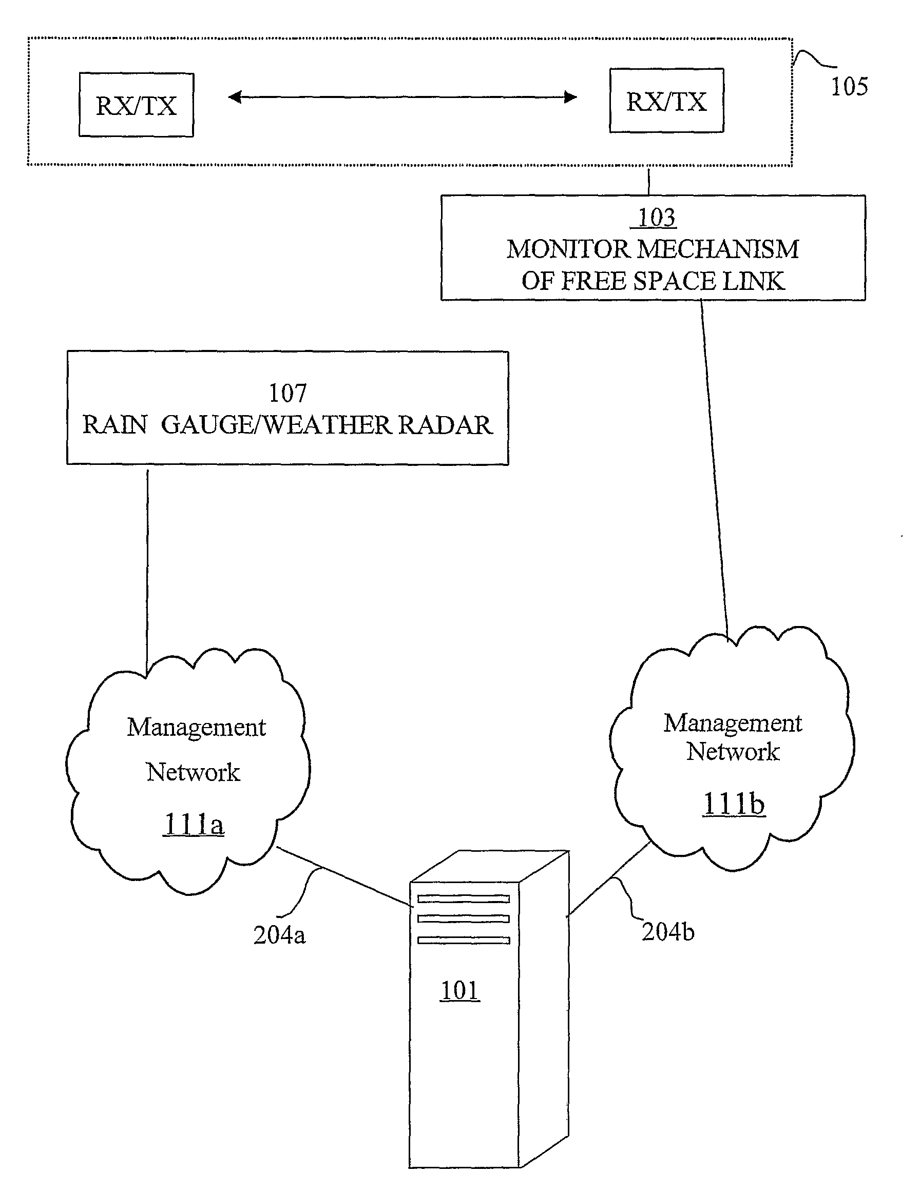
[0029]The present invention is of a system and method for mapping atmospheric phenomena and particularly rainfall rate in a geographic area using previously existing radio infrastructure distributed in the area.

[0030]The principles and operation of a system and method of mapping atmospheric phenomena, e.g. rainfall intensity, in a geographic area using previously existing infrastructure distributed in the area, according to the present invention, may be better understood with reference to the drawings and the accompanying description.

[0031]Before explaining embodiments of the invention in detail, it is to be understood that the invention is not limited in its application to the details of design and the arrangement of the components set forth in the following description or illustrated in the drawings. The invention is capable of other embodiments or of being practiced or carried out in various ways. Also, it is to be understood that the phraseology and terminology employed herein i...


PUM


Abstract

A computerized system for mapping an atmospheric phenomenon in a geographic region. Multiple free-space electromagnetic communications links are previously distributed in the geographic region. The system includes an interface to monitoring mechanisms attached respectively to the free-space electromagnetic communications links. The monitoring mechanisms respectively monitor attenuation levels of the free-space electromagnetic communications links. A processor simultaneously processes the attenuation levels, and maps in the geographic region the atmospheric phenomenon. The simultaneous processing preferably applies a non-linear model which relates the attenuation levels the atmospheric phenomenon, and solves a tomographic problem based on the non-linear model and the attenuation levels. The tomographic problem is preferably solved by an interactive algorithm based on consecutive refinement and linear inversion at each iteration. Alternatively, an interpolation is performed based on respective inverse distance from the communications links. Preferably, the interpolation is further based on respective lengths of communications links. A data interface preferably provides to subscribers temporal information related to the atmospheric phenomenon within portions of the geographic region.

Description

FIELD AND BACKGROUND OF THE INVENTION[0001]The present invention relates to monitoring of atmospheric phenomena based on attenuation of radio links and, more particularly, to the estimation and mapping of rainfall rate using previously existing radio links distributed in a geographic area being monitored. Specifically, the method in some embodiments includes linearizing of a non-linear tomographic problem.[0002]Accurate monitoring of atmospheric parameters is of great importance to many applications including weather forecasting, hydrology, flood warning, water planning and pollution regulation. Monitoring is performed using dedicated equipment such as weather radars, disdrometers, and / or rain gauges. Active microwave sensing of the atmosphere is currently used for atmospheric studies. Active microwave sensing involves scattering when the strength of a received signal is measured and ranging when time delay between transmitter and receiver is measured. Weather radars provide informa...

Claims


Application Information

Patent Timeline
Patent Type & Authority Applications(United States)
IPC IPC(8): G01S13/95
CPCG01W1/10G01W1/02G01W1/14
Inventor MESSER-YARON, HAGITALPERT, PINHASZINEVICH, ARTEMGOLDSHTEIN, OREN
Owner RAMOT AT TEL AVIV UNIV LTD
Why Eureka
Try Eureka