Projection display apparatus

Inactive Publication Date: 2009-06-25
JVC KENWOOD CORP A CORP OF JAPAN
View PDF3 Cites 9 Cited by
  • Summary
  • Abstract
  • Description
  • Claims
  • Application Information

AI Technical Summary

Benefits of technology

[0036]A purpose of the present invention is to provide a compact projection display apparatus that can produce high-quality projected images

Problems solved by technology

Typically, a polarization film is used for converting randomly polarized beams into linearly polarized beams, the usage of which is, however, not efficient because it eliminates almost half of the polarized beams.
The technical factors (1) and (2) require a larger liquid crystal display device which results in higher production cost and a drastic modification to optical design.
The reliability of optical components is, however, one big issue for the technical factor (3).
For example, optical components, such as, a polarizer, a wave plate, and a polarization converter suffer lower reliability when light of a high intensity is incident thereon.
Major causes of degradation of such optical components are oxidation and a photochemical reaction.
During each of the oxidation and photochemical reaction, light incident on an organic material causes disruption of the chemical bonding between polymers that constitute the organic material.
The disruption leads to occurrence of clacks or color change, such as, turning yellow.
The incident intense light then promotes the oxidation and photochemical reaction to the organic materials, thus causing lower optical performance, which results in lower reliability of the projection display apparatus 100.
Such problems discussed above cause adverse effects

Method used


Image

  • Projection display apparatus
  • Projection display apparatus
  • Projection display apparatus

Examples


first embodiment

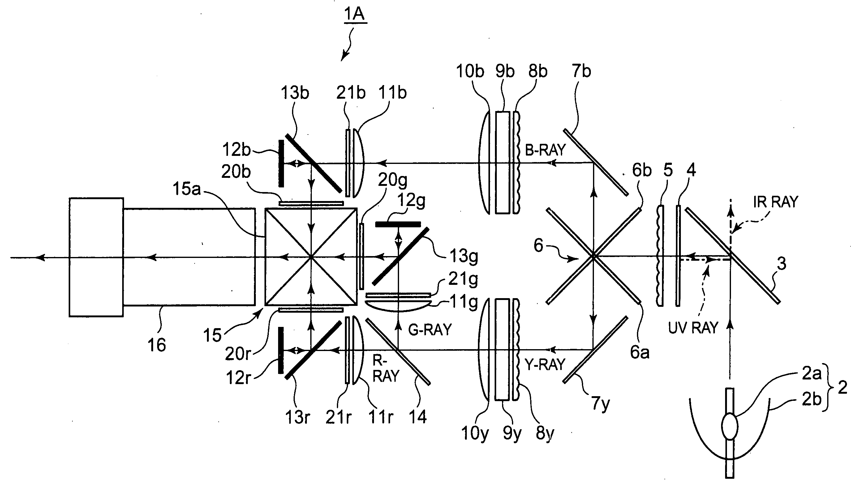
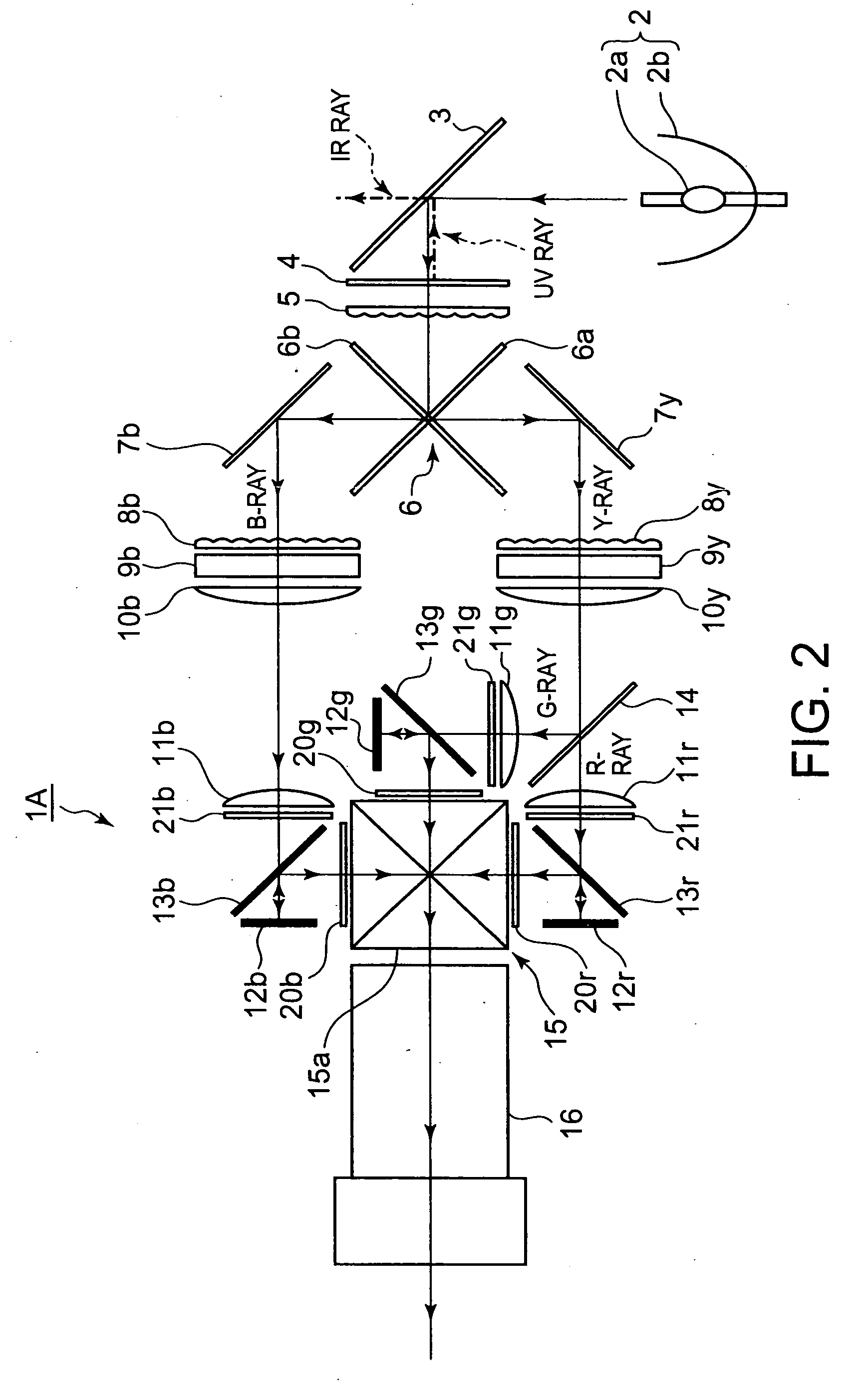
[0051]FIG. 2 shows a schematic illustration of an optical system of a projection display apparatus 1A, as a first preferred embodiment of the present invention.

[0052]As shown in FIG. 2, the optical system of the projection display apparatus 1A is equipped with: a light source 2 having a xenon lamp 2a and a concave mirror 2b; an infrared-ray pass filter 3 that allows an infrared (RF) ray to pass therethrough while reflects the other rays; an ultraviolet-ray reflection filter 4 that reflects an ultraviolet (UV) ray while allows the other rays to pass therethrough; a fly-eye lens 5 (a first lens array) that separates an incident bundle of rays into several sub-bundles of rays; and a cross dichroic mirror 6 (a first color separator) having two dichroic mirrors 6a and 6b that separate the sub-bundles of rays into sub-bundles of rays of a blue ray (referred to as a B-ray, hereinafter) and sub-bundles of rays of a yellow ray (referred to as a Y-ray, hereinafter).

[0053]Moreover, the optical...

second embodiment

[0105]FIG. 5 shows a schematic illustration of an optical system of a projection display apparatus 1B, as a second preferred embodiment of the present invention.

[0106]The same reference numerals or signs are given to the elements of FIG. 5 that are identical or analogous to those of FIG. 2, the detailed explanation thereof being omitted for brevity.

[0107]As shown in FIG. 5, the optical system of the projection display apparatus 1B is equipped with a fly-eye lens 5b for B-ray in front of the fly-eye lens 8b and a fly-eye lens 5y for Y-ray in front of the fly-eye lens 8y, instead of the fly-eye lens 5 shown in FIG. 2.

[0108]The fly-eye lenses 5b and 8b constitute a first integrator optical system. The fly-eye lenses 5y and 8y constitute a second integrator optical system.

[0109]The light emitted from the light source 2 is incident on the cross dichroic mirror 6 (a first color separator) after infrared (RF) and ultraviolet (UV) rays are eliminated by the infrared-ray pass filter 3 and ul...

third embodiment

[0114]FIG. 6 shows a schematic illustration of an optical system of a projection display apparatus 1C, as a third preferred embodiment of the present invention.

[0115]The same reference numerals or signs are given to the elements of FIG. 6 that are identical or analogous to those of FIGS. 2 and 5, the detailed explanation thereof being omitted for brevity.

[0116]As shown in FIG. 6, the optical system of the projection display apparatus 1C is equipped with: three integrator optical systems of fly-eye lenses (5b, 8b), (5y, 8g) and (5y, 8r) for B-, G- and R-rays, respectively; three polarization converters 9b, 9g and 9y for B-, G- and R-rays, respectively; and also three condenser lenses 10b, 10g and 10r for B-, G- and R-rays, respectively.

[0117]The light emitted from the light source 2 is incident on the cross dichroic mirror 6 (a first color separator) after infrared (RF) and ultraviolet (UV) rays are eliminated by the infrared-ray pass filter 3 and ultraviolet-ray reflection filter 4,...


PUM


Abstract

A bundle of rays is incident in a lens array and converted into sub-bundles of rays. The sub-bundles of rays are separated by a color separator into first and second sub-bundles of rays of different colors. The first and the second sub-bundles of rays are combined by other lens arrays into a first and a second bundle of rays of uniform illuminance, respectively. The first and second bundle of rays of uniform illuminance are applied polarization beam splitting and then polarization angle conversion by polarization converters, to be converted into first and second linearly polarized beams, respectively. The second linearly polarized beams are separated by a color separator, provided on an optical path of the second linearly polarized beams, into third and fourth linearly polarized beams of different colors. The first, third and fourth linearly polarized beams are modulated by liquid crystal display devices, provided on optical paths of the first, third and fourth linearly polarized beams, respectively, with input video signals into first, second and third modulated beams. The first, second and third modulated beams are combined by a color combiner into a combined bundle of rays to be projected for displaying images carried by the video signals.

Description

CROSS-REFERENCE TO RELATED APPLICATIONS[0001]This application is based on and claims the benefit of priority from the prior Japanese Patent Application Nos. 2007-326992 filed on Dec. 19, 2007, and 2008-226855 filed on Sep. 4, 2008, the entire contents of which is incorporated herein by reference.BACKGROUND OF THE INVENTION[0002]The present invention relates to a projection display apparatus that exhibits high color reproducibility with less damage to optical components against a high-intensity light source.[0003]One of the known projection display apparatuses equipped with reflective liquid crystal display devices is a projection display apparatus equipped with polarization converters that exhibits high light utilization efficiency with a comparatively simple structure.[0004]Such a projection display apparatus equipped with polarization converters is disclosed in Japanese unexamined Patent Application Publication No. 2000-321662 (referred to as Citation 1, hereinafter).[0005]In the ...

Claims


Application Information

Patent Timeline
IPC IPC(8): G03B21/14
CPCG03B21/14G03B21/208G03B21/2073
Inventor KOBAYASHI, TATSURUHAYAMA, AKIOKAWAMURA, KOUICHINISHIMA, RYO
Owner JVC KENWOOD CORP A CORP OF JAPAN
Why Eureka
Try Eureka