Compact folded thin lens

a thin lens, compact technology, applied in the field of compact thin lens, can solve the problems of over 7 mm in thickness of the folded zoom lens assembly of takeuchi, relatively high cost, and relatively thick zoom lens assembly described by takeuchi, and achieve the effects of low cost, good optical performance and low cos

Inactive Publication Date: 2009-06-25
MONUMENT PEAK VENTURES LLC
View PDF13 Cites 63 Cited by
  • Summary
  • Abstract
  • Description
  • Claims
  • Application Information

AI Technical Summary

Benefits of technology

[0008]The invention describes a low cost folded optical assembly for an image capture device that has a thickness that is less then 7 mm. The low cost folded optical assembly includes two plastic prisms with optical power to provide good optical performance in a very thin form factor at a low cost.

Problems solved by technology

Takeuchi's folded zoom lens assembly is over 7 mm in thickness and it would be relatively expensive since it is composed of five lenses, one prism, and one filter.
As a result, the zoom lens assembly described by Takeuchi is relatively thick and relatively expensive.
A problem with the design described by Nagata is that multiple free form surfaces are used.
Free form surfaces are not rotationally symmetric and as such the mold components for molding the lenses are not manufacturable with rotationally based tooling processes such as diamond turning or traditional grinding and polishing so that manufacturing costs are substantially increased.
This folded zoom lens assembly would also be relatively expensive since the embodiments described include glass lens elements and prisms.
In addition, the lens elements between the two prisms are movable to provide the zoom function which requires complicated guidance mechanisms.

Method used


Image

  • Compact folded thin lens
  • Compact folded thin lens
  • Compact folded thin lens

Examples


example 1

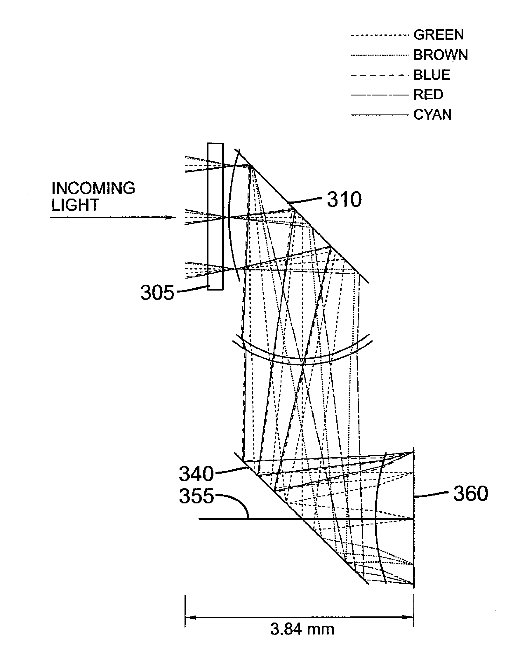
[0041]Ray trace schematics for a lens with moderate angle field of view designed as an example of the invention is shown in a Z-shaped layout in FIG. 3 and a U-shaped layout in FIG. 4. The optical performance and the optical surfaces are the same for both the Z-shaped layout and the U-shaped layout. A description of the lens design including surface curvatures, lateral distances, aperture sizes and materials is given in Table 2 below. The lens is designed for an f# of 3.2, a pixel size of 0.002 mm and a sensor with two mega pixels. The modulation transfer function chart is shown in FIG. 6. The difference between the Z-shaped layout and the U-shaped layout versions of the lens are in the thickness dimension of the lens assembly, as can be seen in Table 1 and in FIGS. 3 and 4, the Z-shaped layout lens is 3.84 mm thick while the U-shaped layout lens is only 3.28 mm thick. For clarification, a cross sectional schematic of the U-shaped layout lens assembly with elements 510 and 520 along...

example 2

[0042]Ray trace schematics for a lens with a wider angle field of view designed as an example of the invention is shown in a Z-shaped layout in FIG. 7 and a U-shaped layout in FIG. 8. As in the lenses in Example 1, the optical performance and the optical surfaces are the same for both the Z-shaped layout and the U-shaped layout. A description of the lens design including surface curvatures, lateral distances, aperture sizes and materials is given in Table 3 below. The lens is designed for an f# of 3.2, a pixel size of 0.002 mm and a sensor with two mega pixels. The modulation transfer function chart is shown in FIG. 10. The difference between the Z-shaped layout and the U-shaped layout versions of the lens are in the thickness dimension of the lens assembly, as can be seen in Table 1 and in FIGS. 7 and 8, the Z-shaped layout lens is 3.15 mm thick while the U-shaped layout lens is only 2.56 mm thick. For clarification, a cross sectional schematic of the U-shaped layout lens assembly ...

example 3

[0043]Lenses with a telephoto angle field of view lens and a larger image sensor were designed as yet a further example of the invention. Ray trace schematics for a telephoto lens designed as an example of the invention are shown in a Z-shaped layout in FIG. 11 and a U-shaped layout in FIG. 12. As in the lenses in Examples 1 and 2, the optical performance and the optical surfaces are the same for both the Z-shaped layout and the U-shaped layout. A description of the lens design including surface curvatures, lateral distances, aperture sizes and materials is given in Table 4 below. In this case, the lens is designed for an f# of 3.2, a pixel size of 0.003 mm and a sensor with two mega pixels. The modulation transfer function chart is shown in FIG. 14. The difference between the Z-shaped layout and the U-shaped layout versions of the lens are in the thickness dimension of the lens assembly, as can be seen in Table 1 and in FIGS. 11 and 12, the Z-shaped layout lens is 6.34 mm thick whi...


PUM


Abstract

A thin lens consists of a first optical element which comprises a first refracting surface, wherein incoming light passes through the first refracting surface on a first optical axis. A reflecting surface changes a direction of the incoming light from the first optical axis to a second optical axis. Incoming light on the second optical axis passes through a second refracting surface. A second optical element comprises a first refracting surface, wherein incoming light passes through the first refracting surface on the second optical axis. A reflecting surface changes a direction of the incoming light from the second optical axis to a third optical axis. Incoming light on the third optical axis passes through a second refracting surface. The third optical axis is approximately parallel to, and in opposite direction from, the first optical axis.

Description

FIELD OF THE INVENTION[0001]The invention pertains to a compact, thin lens for portable devices including an image capture device.BACKGROUND OF THE INVENTION[0002]For portable devices such as cellular phone cameras and laptop computer cameras, it is desirable to reduce costs as much as possible and to keep the thickness of the portable device as thin as possible. Folding the optical path of a lens is an excellent way to change the form factor of the optical assembly. Consequently, a folded optical assembly is an attractive alternative for the image capture device in a portable apparatus. It is the goal of the present invention to provide a low cost folded optical assembly for an image capture device wherein the thickness of the optical assembly is less than 7 mm.[0003]Examples of folded optical assemblies can be found in U.S. Pat. Nos. 6,898,023 (Takeuchi), 6,900,950 (Nagata), and U.S. Patent Application Publication No. 2006 / 0092524 (Konno). Takeuchi discloses a zoom lens assembly w...

Claims


Application Information

Patent Timeline
Patent Type & Authority Applications(United States)
IPC IPC(8): G02B17/08
CPCG02B13/002G02B17/086G02B13/007
Inventor BORDER, JOHN N.BIETRY, JOSEPH R.COMPTON, JOHN
Owner MONUMENT PEAK VENTURES LLC
Why Eureka
Try Eureka