

Vane-type compressor
a compressor and valve body technology, applied in the field of compressors, can solve the problems of increasing the number of components, complex structure and its cost, and insufficient guide pins for coil springs, and achieve the effect of easy fixation on the valve body and high accuracy
- Summary
- Abstract
- Description
- Claims
- Application Information
AI Technical Summary
Benefits of technology
Problems solved by technology
Method used
Image

Examples
first embodiment
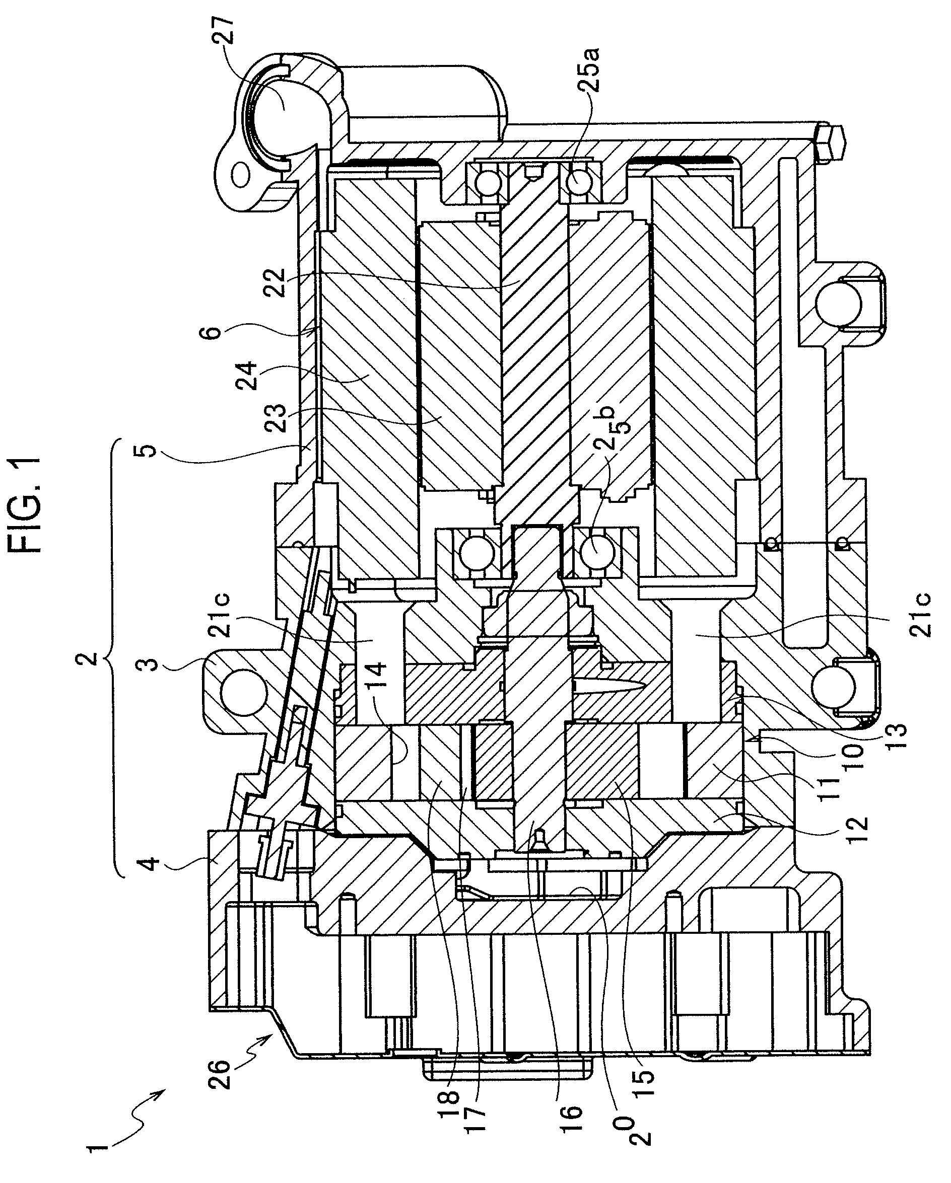
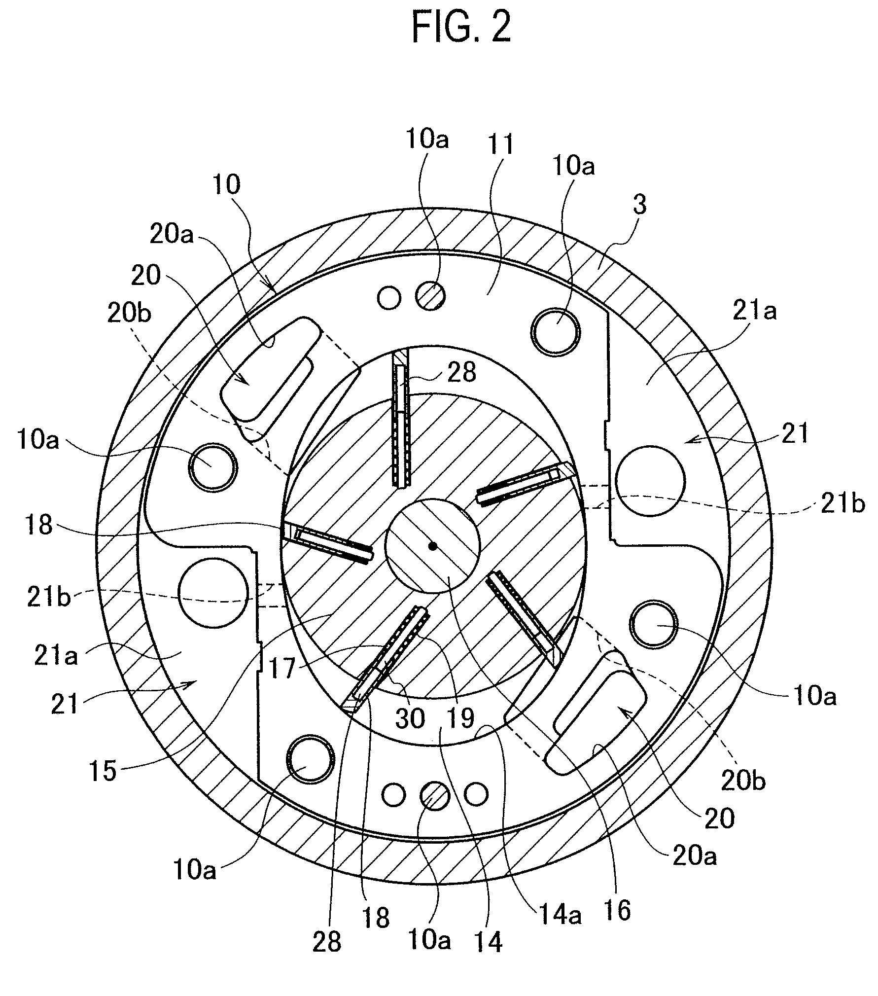
[0057]Hereinafter, embodiments of the prevent invention will be explained with reference to diagrams. First, a first embodiment will be explained with reference to FIGS. 1 to 3.
[0058]As shown in FIG. 1, a compressor 1 includes a housing 2. The housing 2 is configured with an almost tubular compressor housing 3, a front housing 4 provided on one opening end of the compressor housing 3 and a motor housing 5 provided on another opening end of the compressor housing 3. The compressor housings 3, the front housing 4 and the motor housing 5 are all made of aluminum alloy.
[0059]A compression unit 10 is accommodated within the compressor housing 3. The compression unit includes a cylinder block 10, a front block 12 and a rear block both provided besides the cylinder block 11. These blocks 11, 12 and 13 are fixed each other by bolts 10a (see FIG. 2). A compression chamber 14 is formed within the blocks 11, 12 and 13. The blocks 11, 12 and 13 are made of aluminum alloy similarly to the housin...
second embodiment
[0086]A first modified example of the second embodiment is shown in FIGS. 5A and 5B.
[0087]In the first modified example, a spacer 21B is provided between another end of the coil spring 19A and the bottom surface of the vane 18. The spacer 21B projects toward the inside of the coil spring 19A.
[0088]According to the first modified example, compared with the above second embodiment, contacts between the other end of the coil spring 19A and the guide pin 30 can be prevented. Therefore, attrition and breakage of the other end (movable end in relation to the guide pin 30) of the coil spring 19A can be prevented.
[0089]A second modified example of the second embodiment is shown in FIGS. 6A and 6B.
[0090]In the second modified example, the spacer 21B and a spacer 21C are provided between the other end of the coil spring 19A and the bottom surface of the vane 18 and between the other end of the coil spring 19B and the bottom of the vane slot 17. The spacers 21B and 21C project toward the insid...
third embodiment
[0099]A modified example of the third embodiment is shown in FIGS. 8A and 8B.
[0100]In this modified example, an inner diameter of a zero-pitch portion 193 of a coil spring 19D is made smaller than an inner diameter of other portions (except for the zero-pitch portion 193).
[0101]According to this modified embodiment, the zero-pitch portion 193 having the smaller diameter contacts with the guide pin 30 firmly when the coil spring 19d serpentines, so that the other portions never contact with the guide pin 30. Therefore, fatigue breakage of the coil spring 19D can be prevented firmly.
[0102]Note that one zero-pitch portion 192 or 193 is provided at middle of the coil spring 19C or 19D in the third embodiment or its modified example. However, plural zero-pitch portions may be provided for each coil spring.
[0103]Next, a fourth embodiment will be explained with reference to FIGS. 9A and 11. Note that a general configuration of the compressor 1 is the same as that in the first embodiment (s...
PUM
 Abstract
Description
Claims
Application Information