Method and device for ocular alignment and coupling of ocular structures

a technology of ocular alignment and coupling, applied in the field of systems and methods for aligning the eye of a subject, can solve the problems of inability to maintain reliable fixation, surgery may not be able to maintain the desired eye orientation, and adults subjected to extended eye examinations may become tired or subject to other duress

Active Publication Date: 2009-06-25
CARL ZEISS MEDITEC INC
View PDF99 Cites 148 Cited by
  • Summary
  • Abstract
  • Description
  • Claims
  • Application Information

AI Technical Summary

Benefits of technology

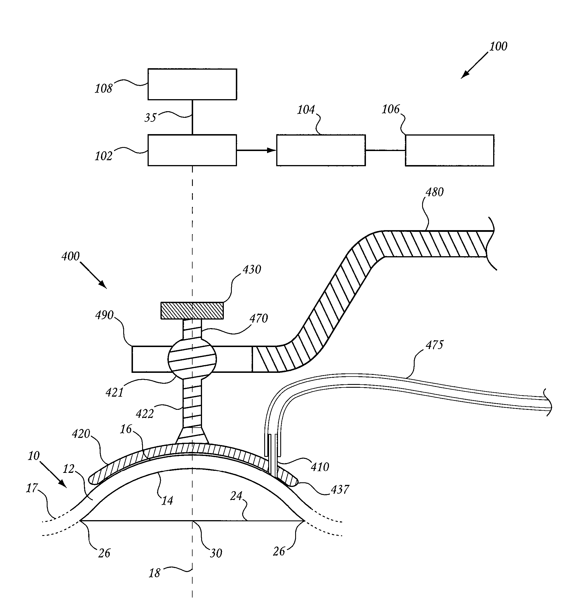
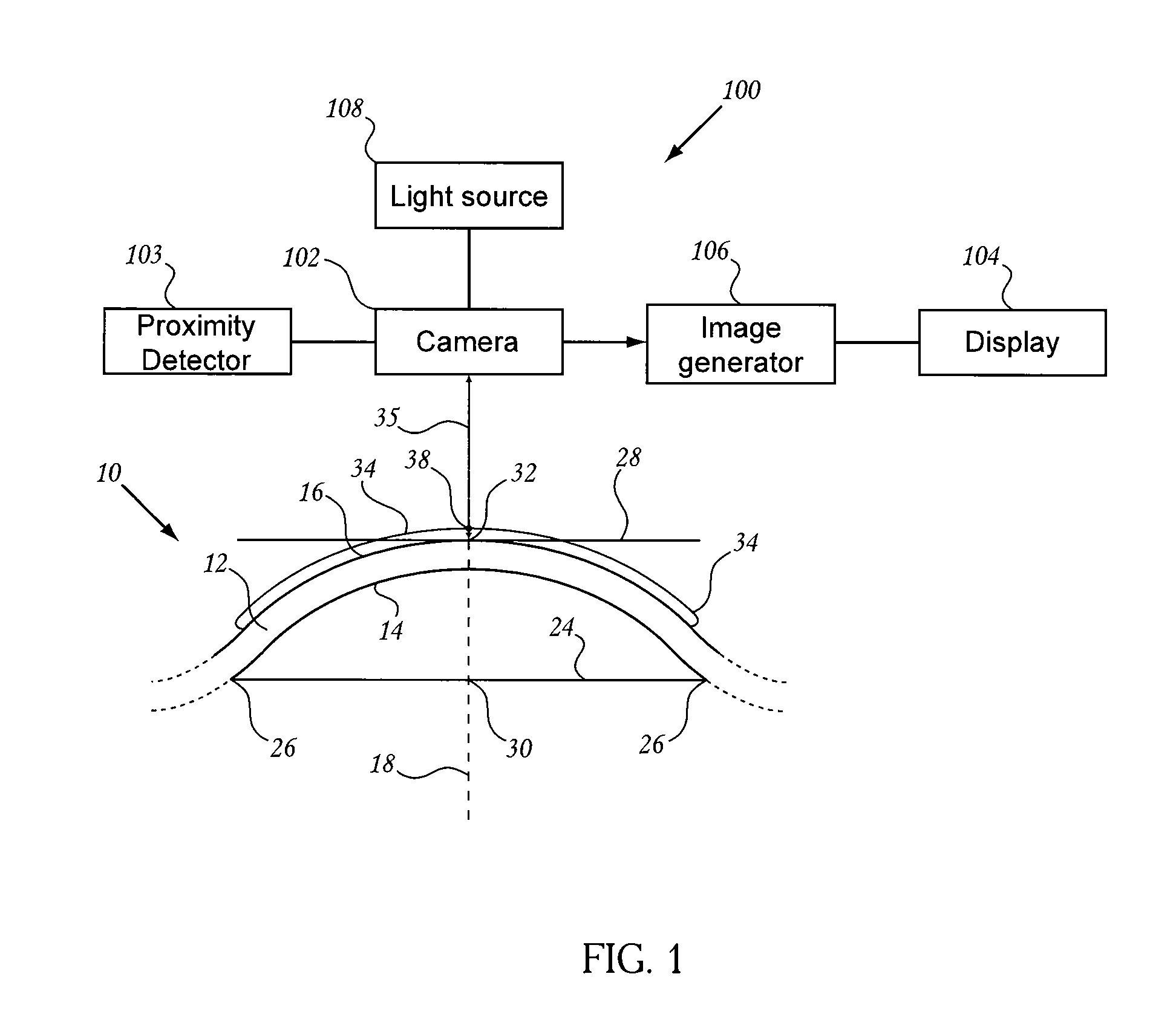
[0031]In yet another embodiment having aspects of the invention, an image-guided ocular treatment system is provided, comprising (a) a head support for supporting a patient's head, (b) a eye guide adapted to be placed on the patient's eye, and stabilized on the eye by the application of negative pressure between the eye guide and eye when the guide is approximately centered with respect the sclera / cornea boundary of the patient's eye, (c) a camera for recording an image of the eye guide on the patient's eye, (d) a guide-alignment assembly for detecting alignment between the eye guide, with such stabilized on a patient's eye, and an external-coordinate reference axis, (e) an external arm pivotally attached to the eye guide to hold the eye at a position in which the eye guide is aligned with the external-coordinate reference axis, (e) a processor operatively connected to the camera and guide-alignment assembly for (i) determining from the image of eye guide and the sclera / cornea boundary, any variation from true centering of the eye guide on the patient's eye, (ii) if variation from true centering is determined, constructing a coordinate transform between the actual and centered positions of the eye guide, (iii) with the eye guide moved to and held at its aligned position, and applying the coordinate transform if necessary, determining the position of the eye with respect to the external-coordinate reference axis, (iv) from the determination in step (iii) determining a treatment axis or axes along which a therapeutic beam will be aimed at a target region of the eye, and (f) a display monitor operatively connected to the processor for displaying to the user, an image of the patient's eye and attached eye guide, information about the extent of alignment between the eye guide and reference beam, and a virtual image of the treatment axis or axis.

Problems solved by technology

Likewise, adults subjected to extended eye examinations may become tired or subject to other duress and fail to maintain reliable fixation.
A patient who is subjected to a therapeutic process such as laser ablation eye surgery may not be able to maintain desired eye orientation over an extended treatment time because of applied anesthesia, fatigue, or distraction by the procedure.
Further, a research animal typically cannot be trained to fixate during eye measurements.
In each of the above cases, the failure or inability of the subject to maintain eye fixation upon an object can produce eye measurements or treatments that are seriously in error.
It is typically a problem to align a patient's eye.
Moreover, there is still debate regarding the proper reference axis for alignment of the eye for treatment, such as laser refractive surgery.
This subjective technique is prone to error which may lead to decentered ablations and other impediments to satisfactory vision correction.

Method used


Image

  • Method and device for ocular alignment and coupling of ocular structures
  • Method and device for ocular alignment and coupling of ocular structures
  • Method and device for ocular alignment and coupling of ocular structures

Examples


Embodiment Construction

[0054]Reference will now be made in detail to disclosed embodiments of the invention, examples of which are illustrated in the accompanying figures.

I. Definitions

[0055]Unless otherwise indicated, all technical and scientific terms used herein have the same meaning as they would to one skilled in the art of the present invention. It is to be understood that this invention is not limited to the particular methodology and protocols described, as these may vary.

[0056]As used herein, “accommodation” refers to the ability to change focus from distant objects to near objects, which ability may tend to diminish with age.

[0057]The term choroid” refers to the highly vascular layer of the eye beneath the sclera.

[0058]As used herein, “ciliary muscle” refers to a muscular ring of tissue located beneath the sclera and attached to the lens via zonules.

[0059]As used herein, “conjunctiva” refers to the thin, transparent tissue covering the outside of the sclera. In some embodiments of the invention,...


PUM


Abstract

Embodiments provide method and systems for determining or measuring objective eye alignment in an external-coordinate system so as to define a reference axis. Additional embodiments provide a method and system of aligning an objectively determined reference axis of the eye in a selected relationship to a therapeutic axis of an ophthalmic therapeutic apparatus and/or a diagnostic axis of an ophthalmic diagnostic apparatus. Embodiments provide a method and system for planning an ophthalmic treatment procedure based on objective eye alignment in an external-coordinate system so as to define a reference axis of an eye to be treated. The reference axis may be used to position a therapeutic energy component, for example, an orthovoltage X-ray treatment device, e.g., positioned to provide treatment to tissue on the retina, such as the macula.

Description

[0001]This application claims the benefit of priority to U.S. Provisional Patent Applications No. 61 / 016,472 filed Dec. 23, 2007 and No. 61 / 020,655 filed Jan. 11, 2008. This Application also claims priority as a continuation-in-part of U.S. patent applications Ser. No. 12 / 027,069, Ser. No. 12 / 027,083, and Ser. No. 12 / 027,094, each filed Feb. 6, 2008. Each of the above applications is incorporated herein in its entirety by reference.[0002]In addition, each of the following commonly-owned US applications are incorporated by reference in their entirety: No. 60 / 933,220 filed Jun. 4, 2007; Ser. No. 11 / 879,843 filed Jul. 18, 2007; Ser. No. 11 / 879,901 filed Jul. 18, 2007; Ser. No. 11 / 833,939 filed Aug. 3, 2007; Ser. No. 11 / 873,386 filed Oct. 16, 2007; Ser. No. 12 / 023,954 filed Jan. 31, 2008; Ser. No. 12 / 023,905 filed Jan. 31, 2008; Ser. No. 12 / 023,968 filed Jan. 31, 2008; Ser. No. 12 / 024,934 filed Feb. 1, 2008; Ser. No. 12 / 023,884 filed Jan. 31, 2008; and Ser. No. 12 / 026,507 filed Feb. 5, ...

Claims


Application Information

Patent Timeline
Patent Type & Authority Applications(United States)
IPC IPC(8): A61B3/15A61B3/14
CPCA61B3/113A61B3/12A61B3/152A61F9/008A61F9/00802A61F9/009A61B3/14A61F2009/00863A61N5/1017A61N5/1049A61N2005/1059A61N2005/1091A61F2009/00846
Inventor GERTNER, MICHAELARNOLDUSSEN, MARKHERRON, MATTLIANG, JUNZHONG
Owner CARL ZEISS MEDITEC INC
Why Eureka
Try Eureka