Manipulator system and method of controlling manipulator

Inactive Publication Date: 2009-06-25
KK TOSHIBA
View PDF3 Cites 64 Cited by
  • Summary
  • Abstract
  • Description
  • Claims
  • Application Information

AI Technical Summary

Benefits of technology

[0013]It is one of the objects of the present invention to provide a manipulator system and a method of controlling a manipulator for reliably returning a worki

Problems solved by technology

Therefore, even when the motors are returned to their original states, the working unit may not fully be returned to its initial position, but may suffer from a positional error, due to inevitable stretching of the wires and friction between the various parts.
If the sensor is incorporated in a medical manipulator, then the working unit becomes large and heavy

Method used


Image

  • Manipulator system and method of controlling manipulator
  • Manipulator system and method of controlling manipulator
  • Manipulator system and method of controlling manipulator

Examples


Example

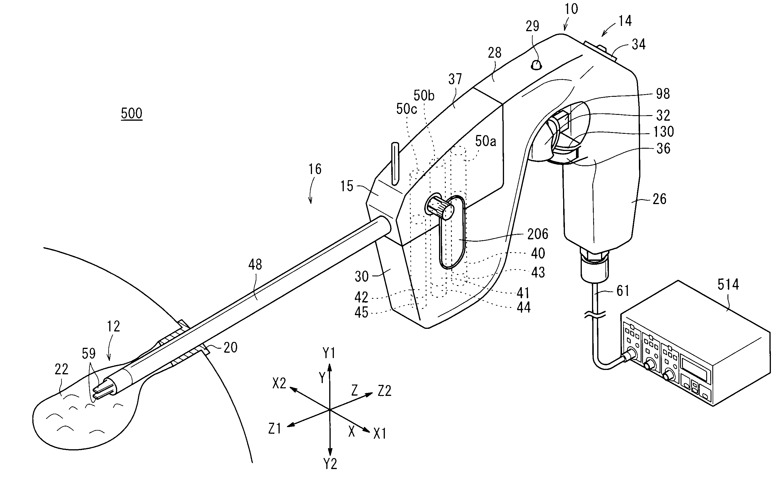
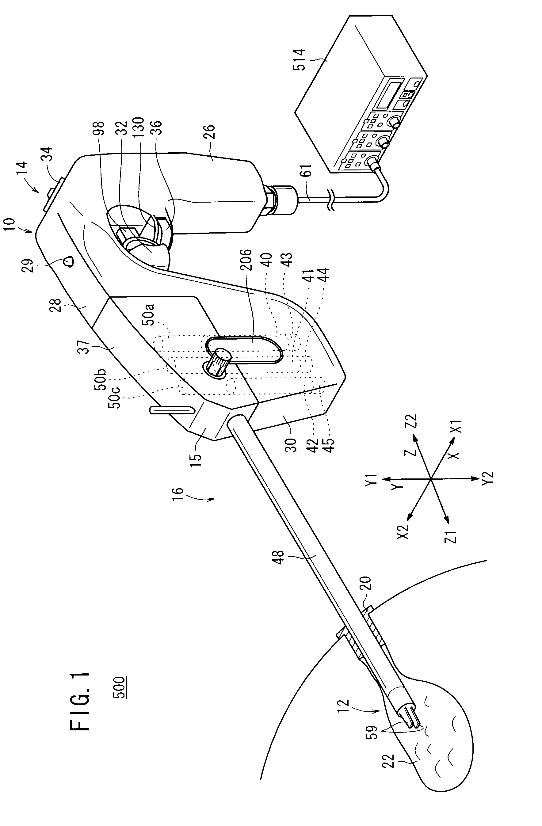
[0033]A manipulator system 500 according to an embodiment of the present invention will be described below with reference to FIGS. 1 through 14. The manipulator system 500 (see FIG. 1) may be used in a laparoscopic surgical operation process or the like.

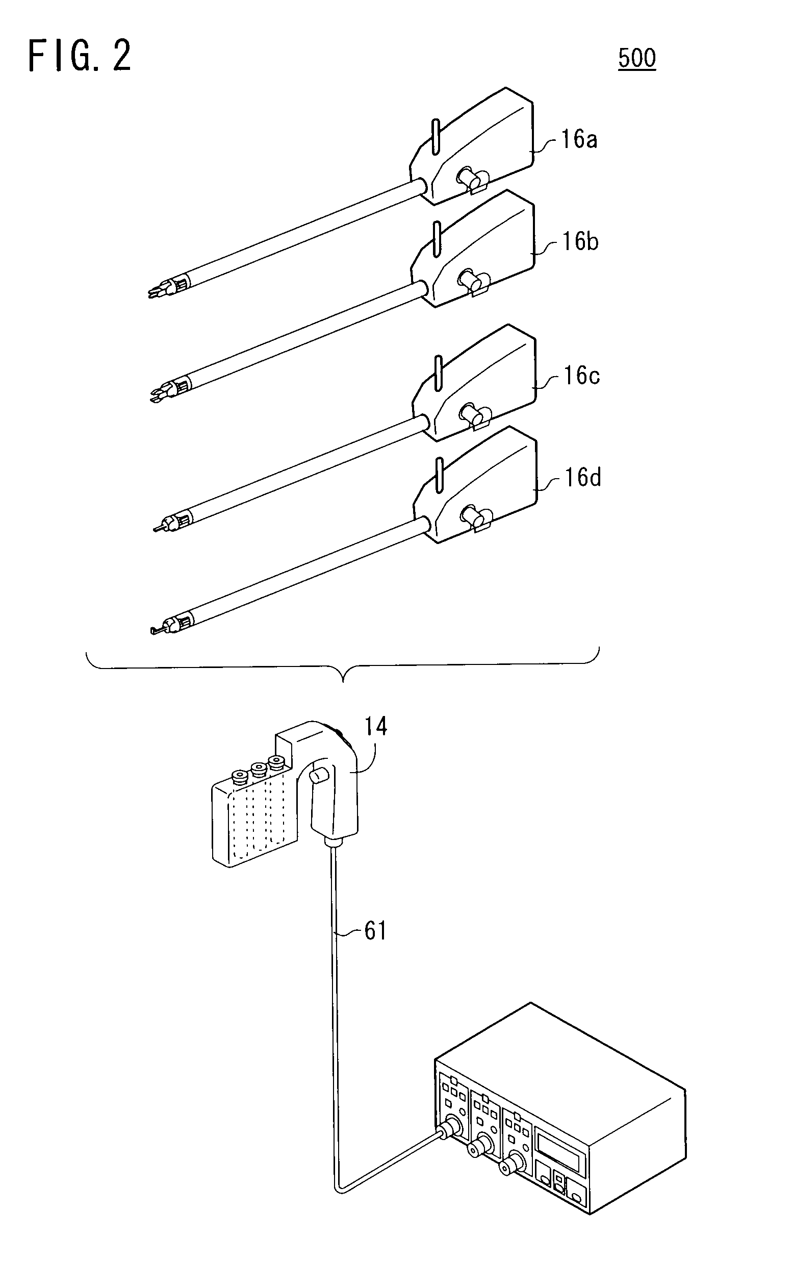
[0034]As shown in FIG. 1, the manipulator system 500 comprises a manipulator 10 and a controller 514 for controlling the manipulator 10. The manipulator 10 and the controller 514 are detachably connected to each other by a connector.

[0035]The manipulator 10 includes a distal-end working unit 12 for gripping a portion of a living tissue, or for gripping a curved needle or the like, for performing a given surgical treatment. The manipulator 10 comprises an operating unit (first portion) 14 and a working unit (second portion) 16 as basic components. The controller 514 electrically controls the manipulator 10, and is connected by the connector to a cable 61 that extends from the lower end of a grip handle 26 of the operating unit 14.

[003...


PUM


Abstract

A medical manipulator system includes a manipulator including a working unit having a distal-end working unit, the attitude of which can be changed by a motor, and a controller for controlling the manipulator. When the controller performs an origin return process for moving a gripper of the distal-end working unit to an origin position at an end of an operating range thereof, the controller issues a first control target value to the motor indicative of a virtual position beyond the origin. Thereafter, the controller issues a second control target value to the motor indicative of the origin. The first control target value represents a position, which is over from the origin P0 by a distance greater than a value corresponding to an error ε between a control target position for the gripper and the actual position thereof.

Description

BACKGROUND OF THE INVENTION[0001]1. Field of the Invention[0002]The present invention relates to a manipulator system including a manipulator having an actuating unit, which can be actuated by an actuator in order to change the attitude thereof, and a controller for controlling the manipulator. The present invention also concerns a method of controlling such a manipulator.[0003]2. Description of the Related Art[0004]According to a laparoscopic surgical operation process, small holes are opened in the abdominal region, for example, of a patient, and an endoscope, forceps or manipulators, etc., are inserted into the holes. A surgeon performs a surgical operation on the patient with the manipulators or forceps while watching an image captured by the endoscope and displayed on a display monitor. Since the laparoscopic surgical operation process does not require a laparotomy to be performed, it is less burdensome on the patient and greatly reduces the number of days that the patient is r...

Claims


Application Information

Patent Timeline
IPC IPC(8): A61B17/29
CPCA61B19/22A61B19/2203A61B2017/00482A61B2017/00477A61B2019/2234A61B2019/2242A61B2019/2276A61B2019/2223A61B34/70A61B34/30A61B34/37A61B34/71A61B2034/305A61B2034/742
Inventor SUNAOSHI, TAKAMITSUJINNO, MAKOTOKATSUKI, RYOHEI
Owner KK TOSHIBA
Why Eureka
Try Eureka