Inspection matrix generation method, encoding method, communication device, communication system, and encoder

a technology of encoding method and inspection matrix, applied in the field of encoding technology in digital communications, can solve problems such as general performance degradation, and achieve the effect of reducing circuit scale and facilitating generation

Inactive Publication Date: 2009-06-25
MITSUBISHI ELECTRIC CORP
View PDF2 Cites 17 Cited by
  • Summary
  • Abstract
  • Description
  • Claims
  • Application Information

AI Technical Summary

Benefits of technology

[0019]According to the present invention, a predetermined masking rule for generating the irregular matrix is applied to the regular quasi-cyclic matrix in which the specific regularity is given, allowing the irregular parity check matrix with the LDGM structure to be easily generated. Moreover, it is not necessary to generate the generator matrix G as is necessary in the conventional technology, allowing the circuit scale to be greatly reduced.

Problems solved by technology

In addition, when the LDPC codes are designed, performance degradation generally occurs when there are many loops with a short length, and thus it is necessary to increase an internal diameter and to reduce the number of loops with the short length (loop 4, loop 6, or the like).

Method used


Image

  • Inspection matrix generation method, encoding method, communication device, communication system, and encoder
  • Inspection matrix generation method, encoding method, communication device, communication system, and encoder
  • Inspection matrix generation method, encoding method, communication device, communication system, and encoder

Examples


first embodiment

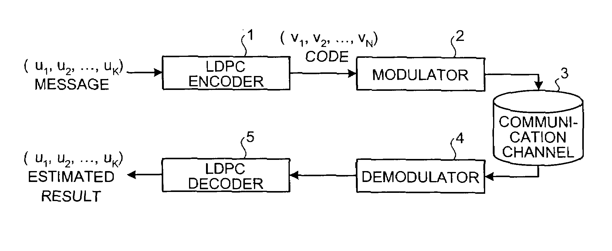
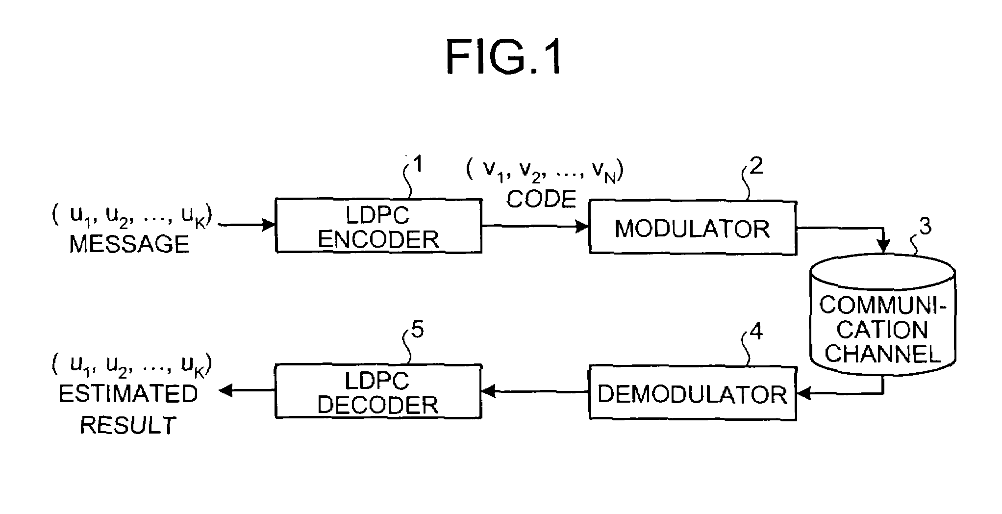
[0051]FIG. 1 is a view showing a configuration example of a communication system including an LDPC encoder and an LDPC decoder according to the present embodiment. In FIG. 1, a communication apparatus (which is called a transmission apparatus) on a transmission-side has a configuration including an LDPC encoder 1 and a modulator 2, and a communication apparatus (which is called a reception apparatus) on a reception-side has a configuration including a demodulator 4 and an LDPC decoder 5.

[0052]Here, a flow of encoding processing and decoding processing in the communication system that employs LDPC codes will be explained briefly.

[0053]The LDPC encoder 1 in the transmission apparatus generates a parity check matrix generated by a check-matrix generating method according to the present embodiment, namely, a parity check matrix HM with M-row×N-column to which masking processing is performed based on a predetermined masking rule described below.

[0054]Thereafter, the LDPC encoder 1 receiv...

second embodiment

[0128]While the code configuration method up to the encoding rate ⅓ is explained in the first embodiment, the code configuration method up to, for example, the encoding rate 1 / 10 will be explained in the present embodiment. Incidentally, a system configuration thereof is similar to that shown in FIG. 1 of the first embodiment. Here, the processing that is different from that in the first embodiment will be explained.

[0129]A masking rule when the quasi-cyclic matrix HQC of 288 (row index j is 0 to 287)×32 (column index l is 0 to 31) corresponding to the encoding rate 1 / 10 is masked with the O-elements of the mask matrix Z with 288-row×32-column will be specifically explained here. Here, the communication apparatus of the present embodiment generates the mask matrix Z for making the quasi-cyclic matrix HQC of 288×32 irregular based on the regular masking rule.

[0130]Hereinafter, the processing different from that shown in FIG. 3 of the first embodiment will be explained as the mask-mat...

third embodiment

[0139]Subsequently, rules when the parity check matrix generated in the first and second embodiments deals with the arbitrary code length will be explained.

[0140]It is possible to deal with the arbitrary code length by changing the size p of the cyclic permutation matrix I(pj,l), and in that case, a value of pj,l is changed base on following rules in the present embodiment.

[0141](1) In “P≦pA”, the value of pj,l is changed as shown in following Equation (21).

pj,llen=pj,lPA mod p  (21)

Note that pj,llen is a column index of 1 of the first row of the cyclic permutation matrices at the time of the size p, and pj,lPA is a column index of 1 of the first row of the cyclic permutation matrices at the time of a size pA, where these pj,lPA and pA shall be determined in advance.

[0142](2) In “p>pA”, the value of pj,l is changed as shown in following Equation (22), following Equation (23), following Equation (24), or Equation (21).

[NumericalExpression13]pj,1len=⌊pj,lpA×(ppA)⌋+⌊ppA×j×1SM×α⌋(22)[Nu...


PUM


Abstract

A regular qc matrix is generated in which cyclic permutation matrices with specific regularity are arranged in row and column directions. A mask matrix supporting multiple encoding rates is generated for making the regular qc matrix into irregular. A specific cyclic permutation matrix in the regular qc matrix is converted into a zero-matrix using a mask matrix corresponding to a specific encoding rate to generate an irregular masking qc matrix. An irregular parity check matrix with a LDGM structure is generated, in which the masking qc matrix and a matrix in which the cyclic permutation matrices are arranged in a staircase manner are arranged in a predetermined location.

Description

TECHNICAL FIELD[0001]The present invention relates to an encoding technology in digital communications, in particular to a check-matrix generating method of generating a parity check matrix for low-density parity check (LDPC) codes, an encoding method of encoding predetermined information bits using the parity check matrix, and a communication apparatus.BACKGROUND ART[0002]Hereinafter, a conventional communication system that employs LDPC codes as an encoding system will be explained. Here, a case in which quasi-cyclic (QC) codes (see Non-patent Document 1) are employed as one example of the LDPC codes will be explained.[0003]First, a flow of encoding / decoding processing in the conventional communication system that employs the LDPC codes as the encoding system will be explained briefly.[0004]An LDPC encoder in a communication apparatus on a transmission-side (it is called a transmission apparatus) generates a parity check matrix H by a conventional method that will be explained bel...

Claims


Application Information

Patent Timeline
Patent Type & Authority Applications(United States)
IPC IPC(8): H03M13/05G06F11/10
CPCH03M13/116H03M13/1185H03M13/118H03M13/19
Inventor MATSUMOTO, WATARUSAKAI, RUIYOSHIDA, HIDEO
Owner MITSUBISHI ELECTRIC CORP
Why Eureka
Try Eureka