Agitator and suction nozzle for vacuum cleaner having the same

a technology of vacuum cleaner and suction nozzle, which is applied in the field of vacuum cleaner, can solve the problems of affecting the efficiency of agitation, secondary contamination of work surfaces, and obstruction of agitation rotation, so as to achieve the effect of improving the structur

Active Publication Date: 2009-07-02
SAMSUNG ELECTRONICS CO LTD
View PDF4 Cites 5 Cited by
  • Summary
  • Abstract
  • Description
  • Claims
  • Application Information

AI Technical Summary

Benefits of technology

[0010]An aspect of the present disclosure is to address at least the above problems and / or disadvantages and to provide at least the advantages described below. Accordingly, an aspect of the present disclosure is to provide an agitator improved in structure to prevent piling of dust particles inside a suction nozzle, and a suction nozzle of a vacuum cleaner having the agitator.
[0017]According to the present disclosure, air current is generated within the suction nozzle in the direction toward the suction port connected to the extension pipe, to prevent dust particles brushed up by the agitator from piling in the suction nozzle.

Problems solved by technology

However, dust particles (d) hovering around both ends of the suction nozzle 10 are not efficiently drawn, since the vacuum does not influence the ends of the suction nozzle 10 as strongly as it does in the proximity to the connector 11 that connects to the extension pipe 30.
The dust particles (d) staying around both ends of the suction nozzle 10 are eventually piled on both ends, and cause serious problems such as secondary contamination of a work surface, or obstructed rotation of the agitator 20.

Method used


Image

  • Agitator and suction nozzle for vacuum cleaner having the same
  • Agitator and suction nozzle for vacuum cleaner having the same
  • Agitator and suction nozzle for vacuum cleaner having the same

Examples


Embodiment Construction

[0025]Hereinafter, the first and second exemplary embodiments of the present disclosure will be described in detail with reference to the accompanying drawing figures.

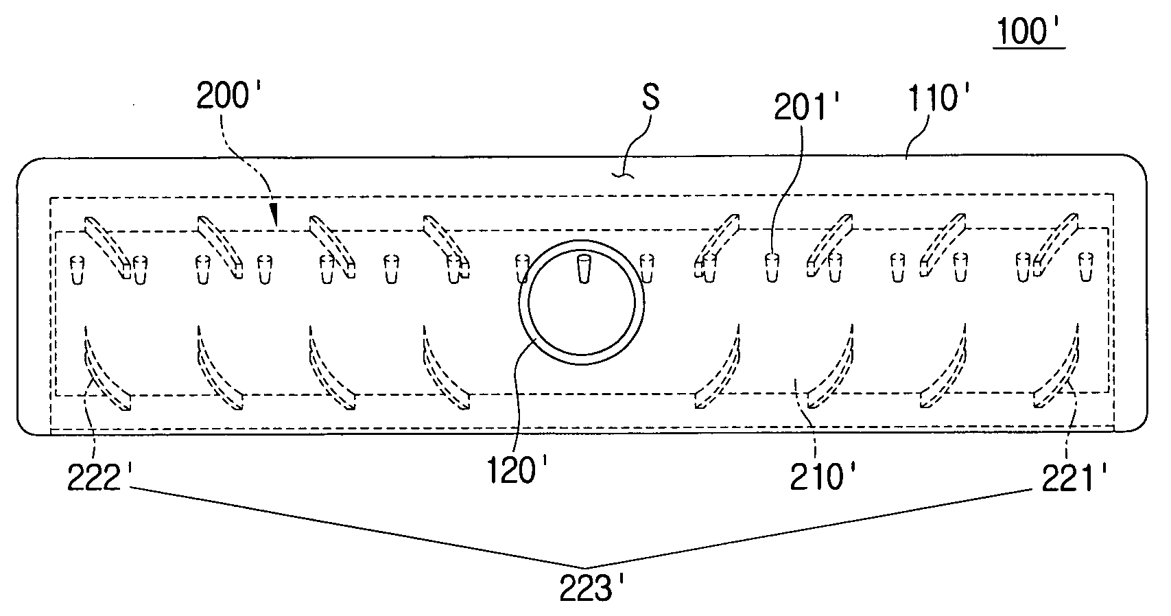
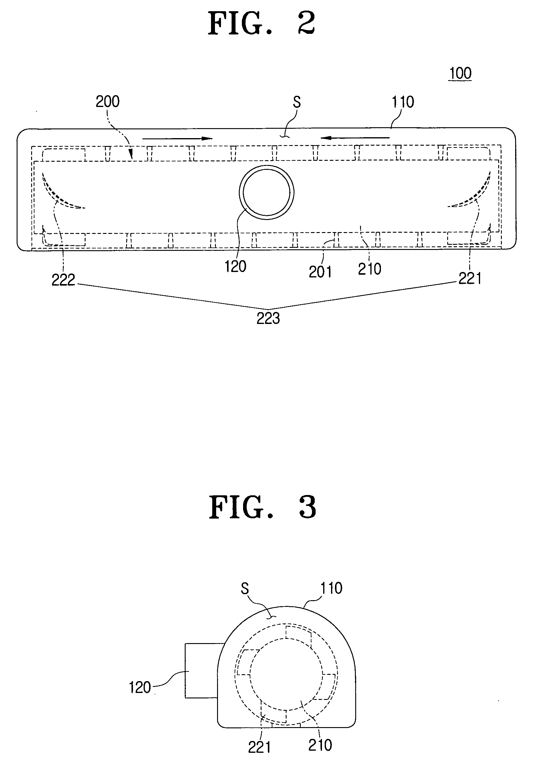
[0026]Referring to FIGS. 2 and 3, a suction nozzle 100 according to a first exemplary embodiment of the present disclosure includes an agitator 200 rotatably accommodated within a suction nozzle body 110.

[0027]The suction nozzle 100 includes a suction port 120. A connector is provided to connect the suction port 120 to an extension pipe, so that the suction port 120 is connected to a main cleaner body (not illustrated).

[0028]The agitator 200 includes an agitator body 210 and an air moving device 223.

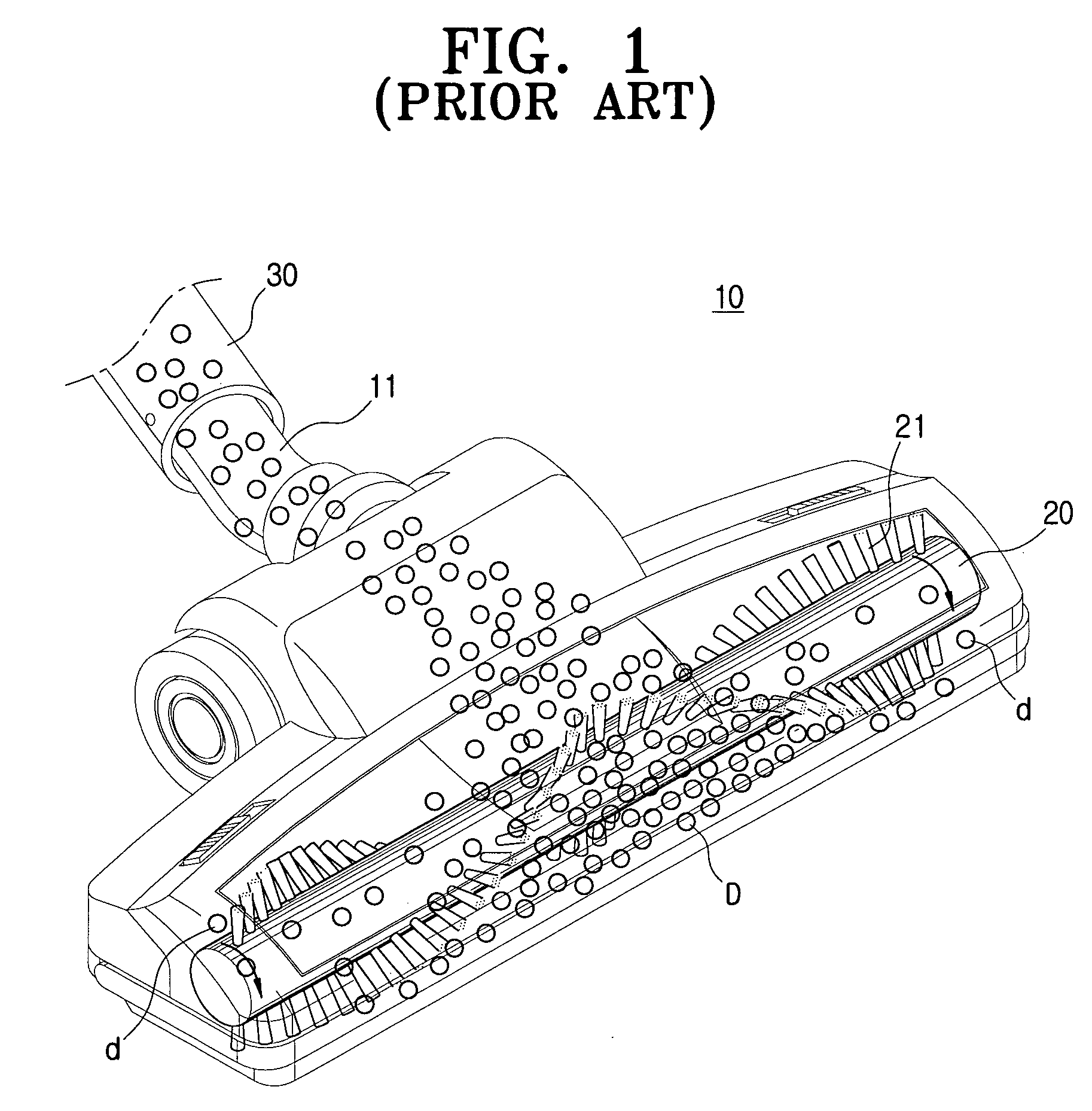
[0029]The agitator body 210 is provided in a cylindrical configuration, and includes a plurality of bristles 201 planed along an outer circumference. The bristles 201 may be planted substantially parallel to an axis of the agitator body 210 (FIGS. 2 and 4), or alternatively, may be planted in a sine wave arrangement (FIG. 1...


PUM


Abstract

An agitator includes an agitator body rotatably accommodated within a suction nozzle having a suction port, and comprising a plurality of bristles planted in an outer circumference, and an air moving device formed on the outer circumference of the agitator body to cause air to move in a space defined between the agitator body and an inner wall of the suction nozzle, if the agitator body is rotated.

Description

CROSS-REFERENCE TO RELATED APPLICATIONS[0001]This application claims the benefit under 35 U.S.C. §119(a) of Korean Patent Application No. 10-2008-0000419, filed on Jan. 2, 2008, in the Korean Intellectual Property Office, the entire contents of which are hereby incorporated by reference.BACKGROUND OF THE INVENTION[0002]1. Field of the Invention[0003]The present disclosure relates to a vacuum cleaner. More particularly, the present disclosure relates to an agitator disposed within a suction nozzle to agitate the air, and a suction nozzle of a vacuum cleaner having the same.[0004]2. Description of the Related Art[0005]A vacuum cleaner uses a negative pressure generated from a vacuum suction motor housed inside a cleaner body to draw in air and dust from an object being cleaned. As the vacuum cleaner draws in air and dust, dust is separated from the indrawn air and collected in a dust separating device.[0006]An agitator having a plurality of bristles planted therein is rotatably accomm...

Claims


Application Information

Patent Timeline
Patent Type & Authority Applications(United States)
IPC IPC(8): A47L5/26
CPCA47L9/0477A47L9/04A47L9/02
Inventor HAN, JUNG-GYUNPARK, JOUNG-SOOLEE, BYUNG-JOKIM, TAE-GWANGKIM, SEE-HYUN
Owner SAMSUNG ELECTRONICS CO LTD
Why Eureka
Try Eureka