

Organic light emitting display
a light-emitting display and organic technology, applied in the field of organic light-emitting displays, can solve the problems of reducing the life span reducing the reliability and reducing the life of organic light-emitting elements
- Summary
- Abstract
- Description
- Claims
- Application Information
AI Technical Summary
Problems solved by technology
Method used
Image

Examples
first embodiment
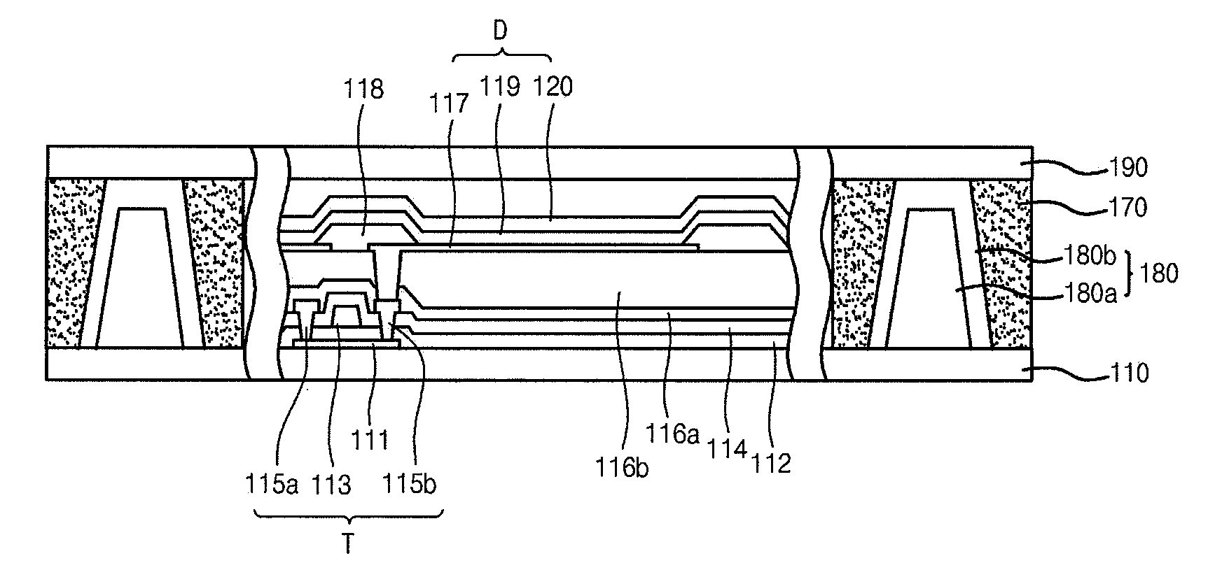
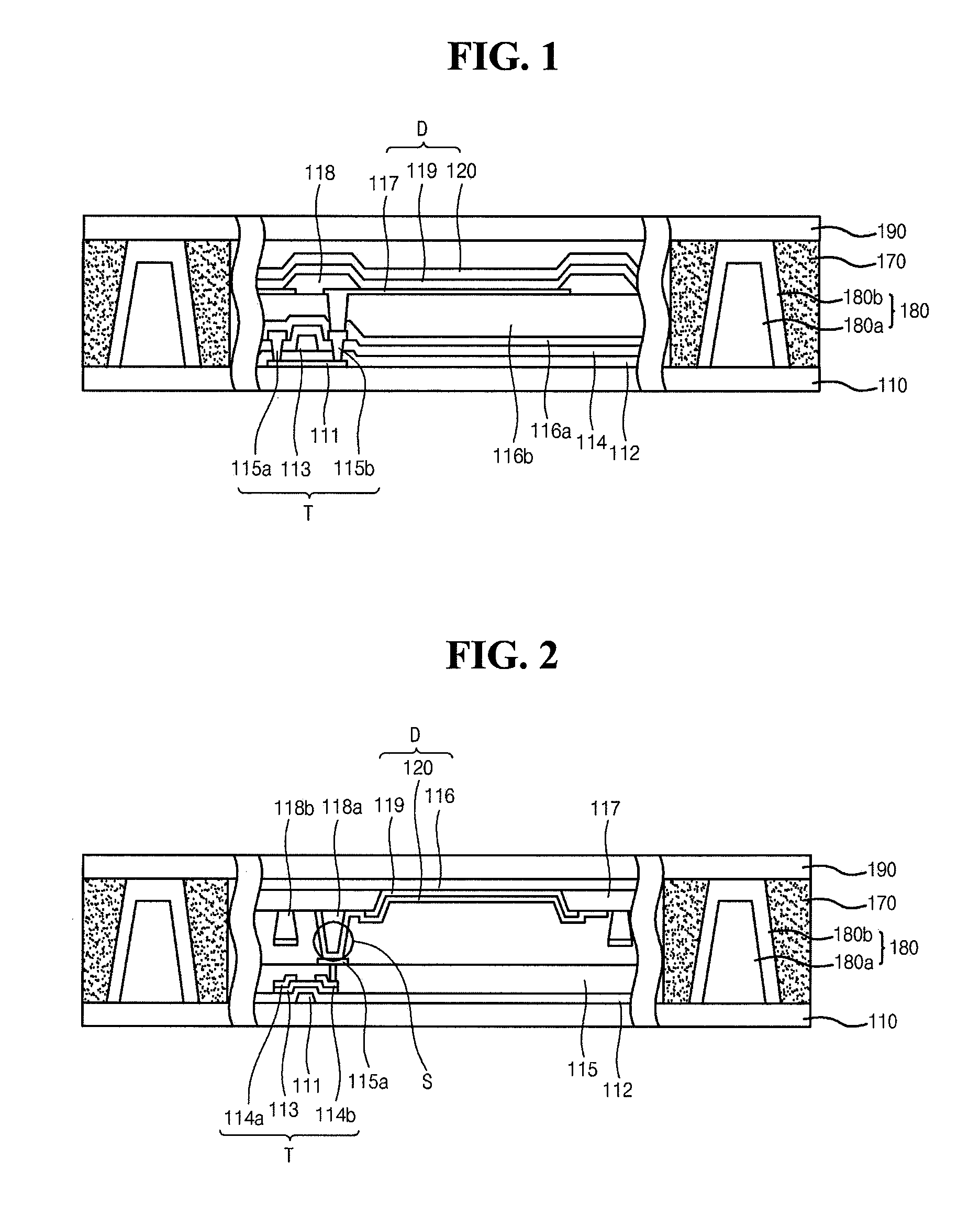
[0022]FIGS. 1 and 2 are cross-sectional views illustrating an organic light emitting display according to a first embodiment of the invention. As shown in FIG. 1, the organic light emitting display includes a first substrate 110 formed of glass, metal, ceramic or plastic such as polycarbonate resin, acrylic resin, vinyl chloride resin, polyethyleneterephthalate (PET) resin, polyimide resin, polyester resin, epoxy resin, silicon resin, and fluoride resin. The first substrate 110 however is not limited to theses materials.
[0023]The organic light emitting display also includes a second substrate 190 that is spaced apart and positioned opposite to the first substrate 110. Further, the second substrate 190 may be formed of any one of the materials of the first substrate 10 depending on a light emitting direction of the organic light emitting display. Also, the organic light emitting display includes a display unit between the first and second substrates 110 and 190. The display unit incl...
second embodiment
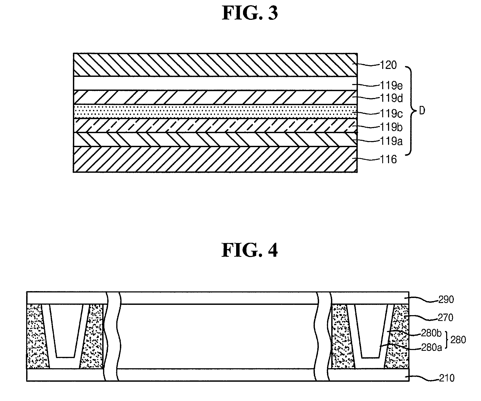
[0055]FIG. 4 is a cross-sectional view of an organic light emitting display according to a second embodiment of the invention. As shown in FIG. 4, the organic light emitting display includes a first substrate 210. The first substrate 210 may be formed of glass, metal, ceramic or plastic such as polycarbonate resin, acrylic resin, vinyl chloride resin, polyethyleneterephthalate (PET) resin, polyimide resin, polyester resin, epoxy resin, silicon resin, and fluoride resin, but is not limited to these materials.
[0056]The organic light emitting display also includes a second substrate 290 that is spaced from and positioned opposite to the first substrate 210. The second substrate 290 may be formed of any one of the formation materials of the first substrate 210 depending on a light emitting direction of the organic light emitting display.
[0057]Further, as discussed in the first embodiment, the organic light emitting display include a display unit between the first and second substrates 2...
third embodiment
[0064]Next, FIG. 5 is a cross-sectional view of an organic light emitting display according to a third embodiment of the invention. As shown in FIG. 5, the organic light emitting display includes a first substrate 310 formed of glass, metal, ceramic or plastic such as polycarbonate resin, acrylic resin, vinyl chloride resin, polyethyleneterephthalate (PET) resin, polyimide resin, polyester resin, epoxy resin, silicon resin, and fluoride resin, but is not limited to these materials.
[0065]The organic light emitting display also includes a second substrate 390 that is spaced from and positioned opposite to the first substrate 310. Further, the second substrate 390 may be formed of any one of the formation materials of the first substrate 310 depending on a light emitting direction of the organic light emitting display.
[0066]In addition, and as discussed above, the organic light emitting display includes a display unit between tie first and second substrates 310 and 390. The structure o...
PUM
| Property | Measurement | Unit |
|---|---|---|
| Shape | aaaaa | aaaaa |
| Water absorption | aaaaa | aaaaa |
Abstract
Description
Claims
Application Information