Light source system

a light source and light source technology, applied in the direction of electric variable regulation, process and machine control, instruments, etc., can solve the problems of increasing the number of members in the system, the emission amount of light sources, and the adverse effect of light reception operation by light-sensing devices, so as to avoid the adverse effect of light reception operation, the effect of large temporal variation in the measurement environment component and increased system members

Active Publication Date: 2009-07-02
SATURN LICENSING LLC
View PDF5 Cites 8 Cited by
  • Summary
  • Abstract
  • Description
  • Claims
  • Application Information

AI Technical Summary

Benefits of technology

[0008]Such a measurement environment component (specifically the background component) causes an adverse effect on light reception operation by a light-sensing device, because the range of temporal variation in the measurement environment component is large due to an influence such as an infrared ray emitted from a remote control of a TV. In other words, such a temporal variation in the background component interfere with proper light reception operation, so in spite of the fact that the light emission amount (luminance) of the light source is in a normal (optimum) state, a detection value by the light-sensing device is not an appropriate value, and as a result, the light emission amount of the light source may be out of an optimum state.
[0009]As a means for avoiding the adverse effect on the light reception operation by such a measurement environment component (specifically the background component), it is considered to arrange an infrared filter or the like on the light-sensing device; however, when such a filter is arranged, the number of members in the system is increased, thereby manufacturing costs are increased.
[0010]In view of the foregoing, it is desirable to provide a light source system capable of controlling the light emission amount of a light source more accurately while keeping manufacturing costs low.

Problems solved by technology

Such a measurement environment component (specifically the background component) causes an adverse effect on light reception operation by a light-sensing device, because the range of temporal variation in the measurement environment component is large due to an influence such as an infrared ray emitted from a remote control of a TV.
In other words, such a temporal variation in the background component interfere with proper light reception operation, so in spite of the fact that the light emission amount (luminance) of the light source is in a normal (optimum) state, a detection value by the light-sensing device is not an appropriate value, and as a result, the light emission amount of the light source may be out of an optimum state.
As a means for avoiding the adverse effect on the light reception operation by such a measurement environment component (specifically the background component), it is considered to arrange an infrared filter or the like on the light-sensing device; however, when such a filter is arranged, the number of members in the system is increased, thereby manufacturing costs are increased.

Method used


Image

  • Light source system
  • Light source system
  • Light source system

Examples


Embodiment Construction

[0027]A preferred embodiment will be described in detail below referring to the accompanying drawings.

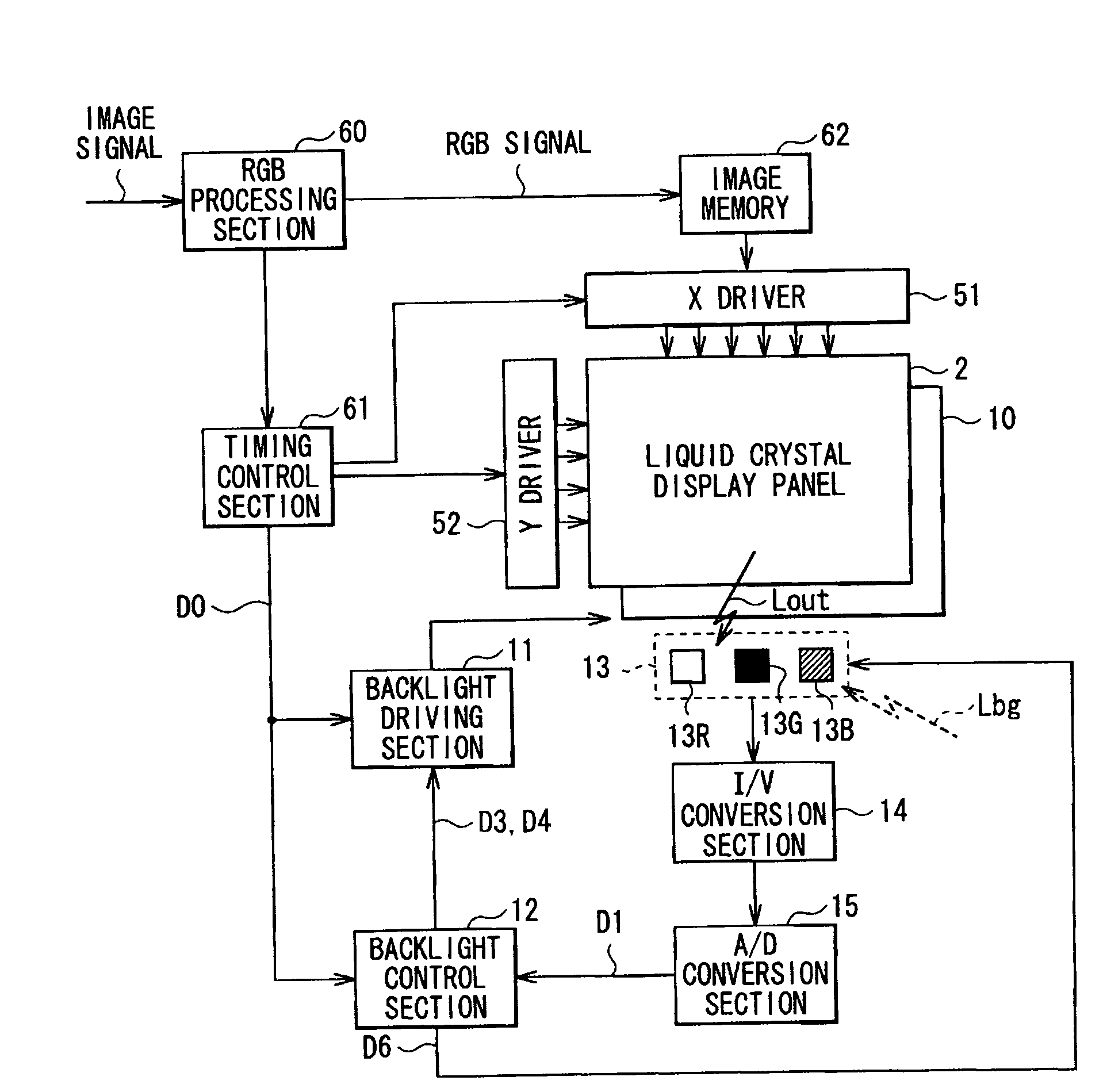
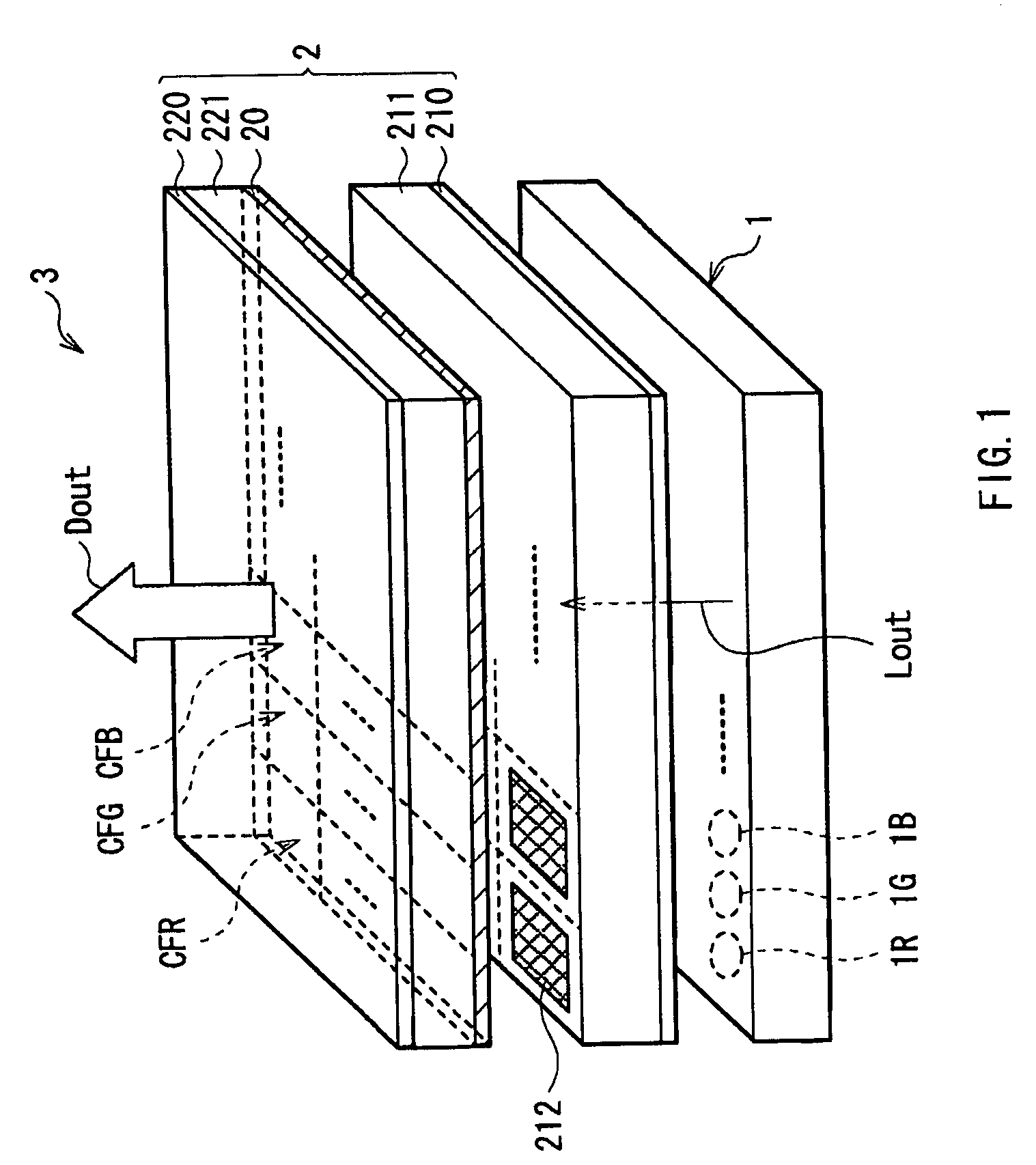
[0028]FIG. 1 shows the whole configuration of an image display system (a liquid crystal display 3) according to an embodiment of the invention. The liquid crystal display 3 is a so-called transmissive liquid crystal display emitting transmitted light as display light Dout, and includes a backlight system 1 as a light source device according to an embodiment of the invention and a transmissive liquid crystal display panel 2. A method of displaying an image according to an embodiment of the invention is embodied by an image display system according to the embodiment, and will be also described below.

[0029]The liquid crystal display panel 2 includes a transmissive liquid crystal layer 20, a pair of substrates between which the liquid crystal layer 20 is sandwiched, that is, a TFT (Thin Film Transistor) substrate 211 as a substrate on a side closer to the backlight system 1 and a facing...


PUM


Abstract

A light source system capable of controlling a light emission amount of a light source section more accurately while keeping manufacturing costs low is provided. The light source system includes a light source, a light-sensing device detecting light from the light source, a calculation means, and a light source control means. The calculation means calculates a net light amount by subtracting a measurement environment component from a light amount detected by the light-sensing device. The measurement environment component is independent of a lighting state in the light source. The light source control means controls the light source on the basis of the net light amount obtained by the calculation means.

Description

CROSS REFERENCES TO RELATED APPLICATIONS[0001]The present invention contains subject matter related to Japanese Patent Application JP 2007-340987 filed in the Japanese Patent Office on Dec. 28, 2007, the entire contents of which being incorporated herein by reference.BACKGROUND OF THE INVENTION[0002]1. Field of the Invention[0003]The present invention relates to a light source system used as, for example, a backlight source of a liquid crystal display.[0004]2. Description of the Related Art[0005]In recent years, flat panel displays as typified by liquid crystal TVs and plasma display panels (PDPs) have become a trend, and among them, most of mobile displays are liquid crystal displays, and precise color reproducibility is desired in the mobile displays. Moreover, as backlights for liquid crystal panels, CCFLs (Cold Cathode Fluorescent Lamps) using fluorescent tubes are mainstream; however, mercury-free light sources are environmentally desired, so light emitting diodes (LEDs) and th...

Claims


Application Information

Patent Timeline
Patent Type & Authority Applications(United States)
IPC IPC(8): H05B37/02
CPCG09G3/3413G09G3/3611G09G2320/064H05B33/0866G09G2360/145H05B33/0827H05B33/086G09G2360/144H05B45/20H05B45/46H05B45/22H05B47/11Y02B20/40H05B45/24
Inventor KATSU, YOSHIHIRO
Owner SATURN LICENSING LLC
Why Eureka
Try Eureka