Imaging apparatus
a technology of imaging apparatus and image acquisition, which is applied in the field of processing an image acquired by an imaging apparatus, can solve the problems of the change in the amount of dark current noise generated in the final exposure and the amount of dark current noise generated in the dark exposure, and the inability to precisely remove the dark current noise from the captured image acquired in the final exposur
- Summary
- Abstract
- Description
- Claims
- Application Information
AI Technical Summary
Benefits of technology
Problems solved by technology
Method used
Image
Examples
first embodiment
1. First Embodiment
[0028]A first embodiment of the invention will be described below with reference to the drawings.
1-1. Configuration
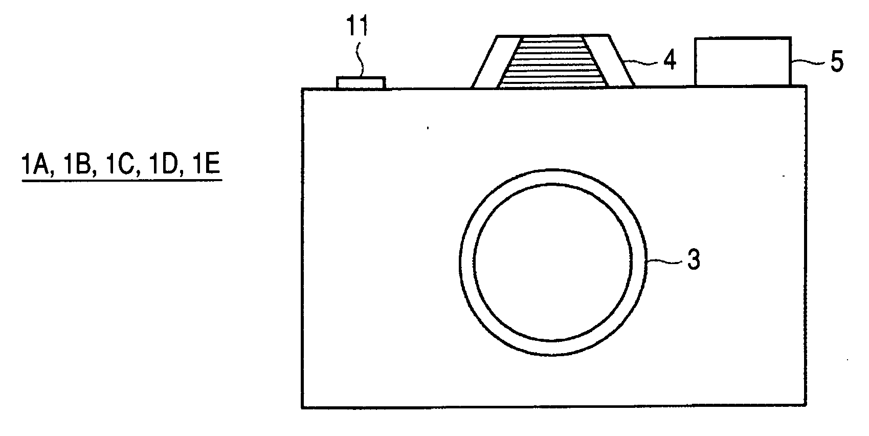
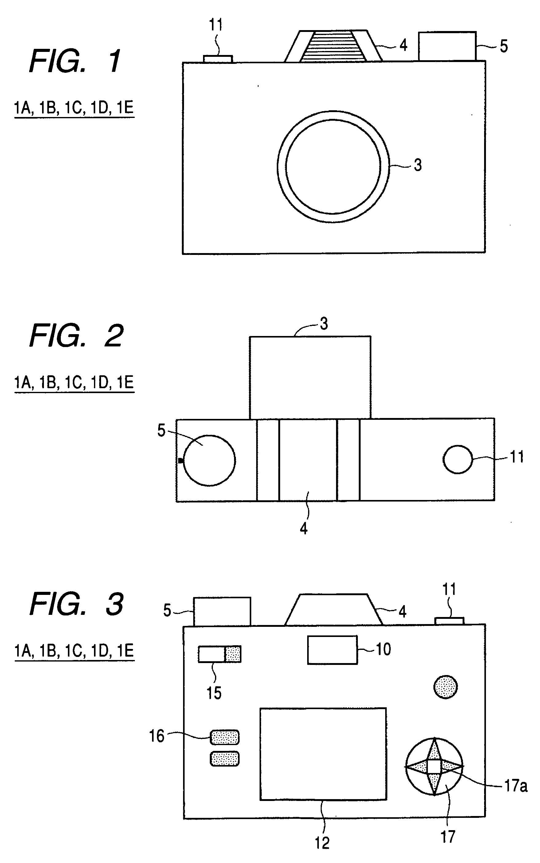
[0029]FIGS. 1, 2, and 3 show an external configuration of an imaging apparatus 1A according to the first embodiment of the invention. FIG. 1 is a front exterior view of the imaging apparatus 1A. FIG. 2 is a top exterior view of the imaging apparatus 1A. FIG. 3 is a rear exterior view of the imaging apparatus 1A.
[0030]The imaging apparatus 1A is configured as a digital camera, and includes an imaging lens 3 in a front portion of the imaging apparatus 1A (see FIG. 1).
[0031]The imaging lens 3 mainly includes a group of lenses, an aperture, and other components. The group of lenses includes a focusing lens that moves in the optical axis direction to change the position of the focal point.
[0032]The imaging apparatus 1A further includes a release button (shutter button) 11 for instructing the apparatus to start exposure, a flash 4, and a mode dial 5 on the ...
second embodiment
2. Second Embodiment
[0093]A second embodiment of the invention will be described. In an imaging apparatus 1B according to the second embodiment, in an extended exposure, the period in which dark exposure is carried out (dark exposure period) is set to be shorter (a shorter period) than the final exposure period. FIG. 10 is a schematic diagram of noise removal carried out in the imaging apparatus 1B.
[0094]The imaging apparatus 1B according to the second embodiment has the same configuration and functions as those of the imaging apparatus 1A according to the first embodiment (see FIGS. 1 to 6) except that the dark exposure period in extended exposure imaging is shorter than the final exposure period. The common portions have the same reference characters and description thereof will be omitted.
[0095]As shown in FIG. 10, since the dark exposure period is set to a smaller value, the dark noise accumulated value BI (N) acquired by the noise data acquisition section 310 and the pixel valu...
third embodiment
3. Third Embodiment
[0099]A third embodiment of the invention will be described. In an imaging apparatus 1C according to the third embodiment, the noise data acquisition section 310 monitors the dark noise accumulated value BI acquired in the dark exposure, and the dark exposure is terminated when the data amount of the dark noise accumulated value BI becomes substantially the same as that of the noise accumulated value Hi. FIG. 11 is a block diagram showing a functional configuration of the imaging apparatus 1C. FIG. 12 is a schematic diagram of noise removal carried out in the imaging apparatus 1C.
[0100]The imaging apparatus 1C according to the third embodiment has the same configuration and functions as those of the imaging apparatus 1A according to the first embodiment (see FIGS. 1 to 3, FIGS. 5 and 6) except that the dark noise accumulated value BI is monitored and the dark exposure is terminated when the dark noise accumulated value BI becomes substantially the same as the nois...
PUM
 Abstract
Description
Claims
Application Information
 - R&D
- Intellectual Property
- Life Sciences
- Materials
- Tech Scout
- Unparalleled Data Quality
- Higher Quality Content
- 60% Fewer Hallucinations
Browse by: Latest US Patents, China's latest patents, Technical Efficacy Thesaurus, Application Domain, Technology Topic, Popular Technical Reports.
© 2025 PatSnap. All rights reserved.Legal|Privacy policy|Modern Slavery Act Transparency Statement|Sitemap|About US| Contact US: help@patsnap.com


