Oblique projection optical system

a projection optical system and optical system technology, applied in optics, projectors, instruments, etc., can solve the problems of inefficient aberration correction, large mirror size, and difficult to achieve compactness of projection optical systems

Active Publication Date: 2009-07-02
KONICA MINOLTA OPTO
View PDF7 Cites 41 Cited by
  • Summary
  • Abstract
  • Description
  • Claims
  • Application Information

AI Technical Summary

Problems solved by technology

However, in the oblique projection optical system described in the Patent Document 1, because the convex mirror's optical power is weak, the mirror size is large.
Accordingly, it is difficult to achieve compactness of the projection optical system.
Besides, in the oblique projection optical system described in the Patent Document 1, because the distance between the concave mirror and the convex mirror is short, aberration correction is inefficient.
In addition, because there are only two reflection surfaces that are disposed as optical surfaces in the vicinity of and after the intermediate image, the burden of aberration correction on the reflection surfaces is heavy, and it is concerned that error sensitivity and size would increase.

Method used


Image

  • Oblique projection optical system
  • Oblique projection optical system
  • Oblique projection optical system

Examples


example 1

FnoY=4.77, FnoZ=4.64

Example 2: β=109.6, FnoY=3.00, FnoZ=2.97

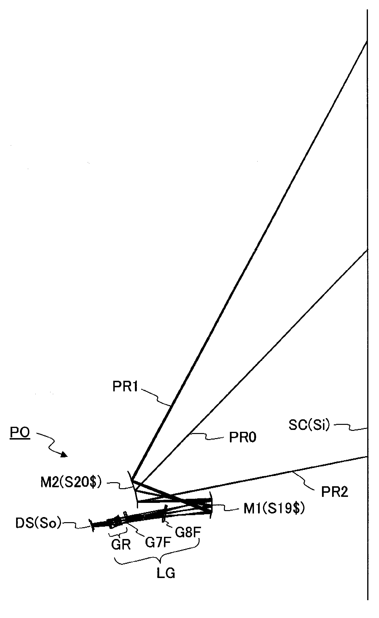
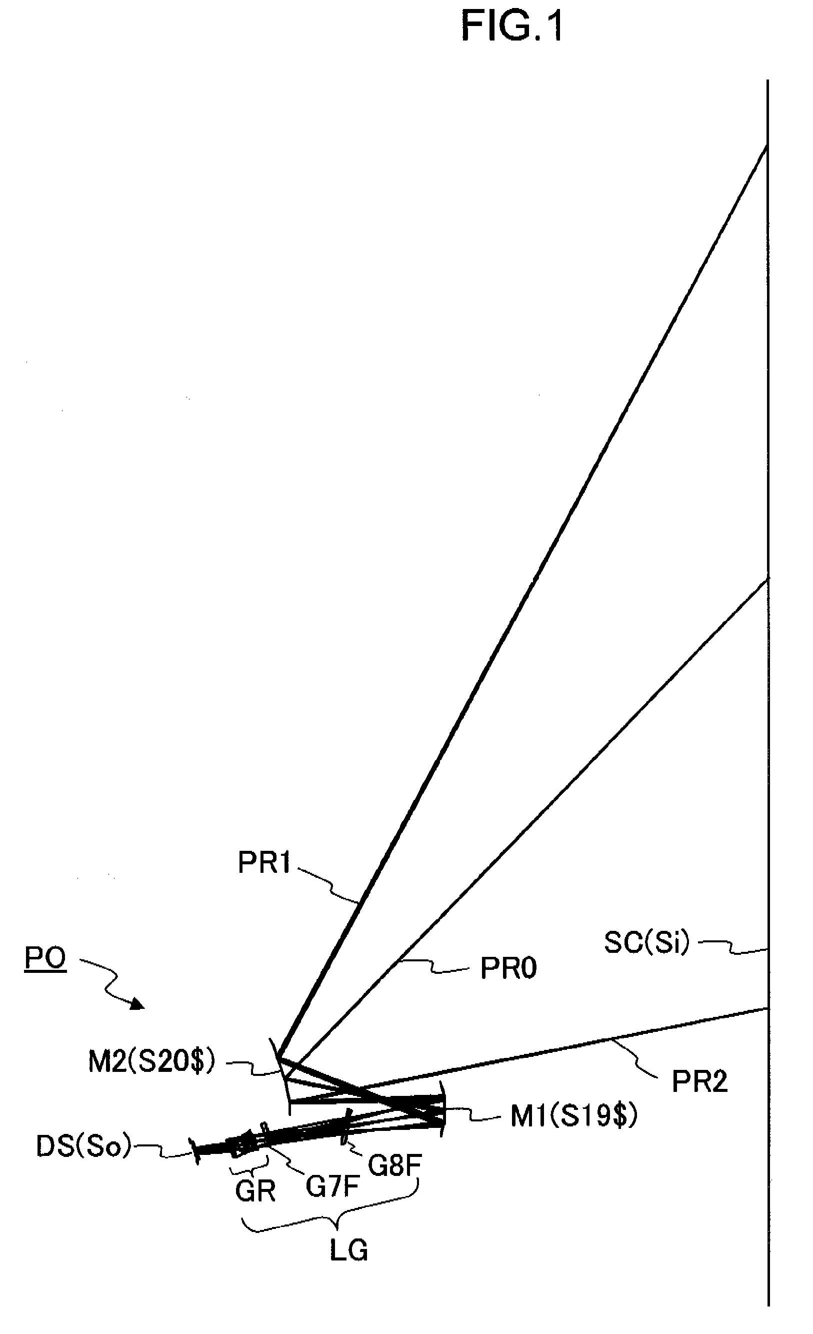
[0113]Spot diagrams in the examples 1 and 2 are each shown in FIGS. 5 and 6. The spot diagrams show the imaging performance on the screen surface Si in terms of 3 wavelengths (460 nm, 546 nm, 620 nm) and 25 evaluation points. The scale in each spot diagram is ±1 mm. The coordinates (Y, Z) in FIGS. 5 and 6 are the local coordinates (Y, Z; mm; e-n=×10−n) on the screen surface Si that shows a projection position of the spot centroid at each evaluation point. Because both examples are composed of a plane-symmetric optical system with respect to the XY plane, the spot diagrams show only the half on the plus side in the Z direction on the screen surface Si, and the remaining half is not shown. These evaluation points are conjugate with the divisional points that are obtained by equally dividing longitudinally and transversely the half of the display device surface So in the Z direction into 4 parts. An ideal image formation point...


PUM


Abstract

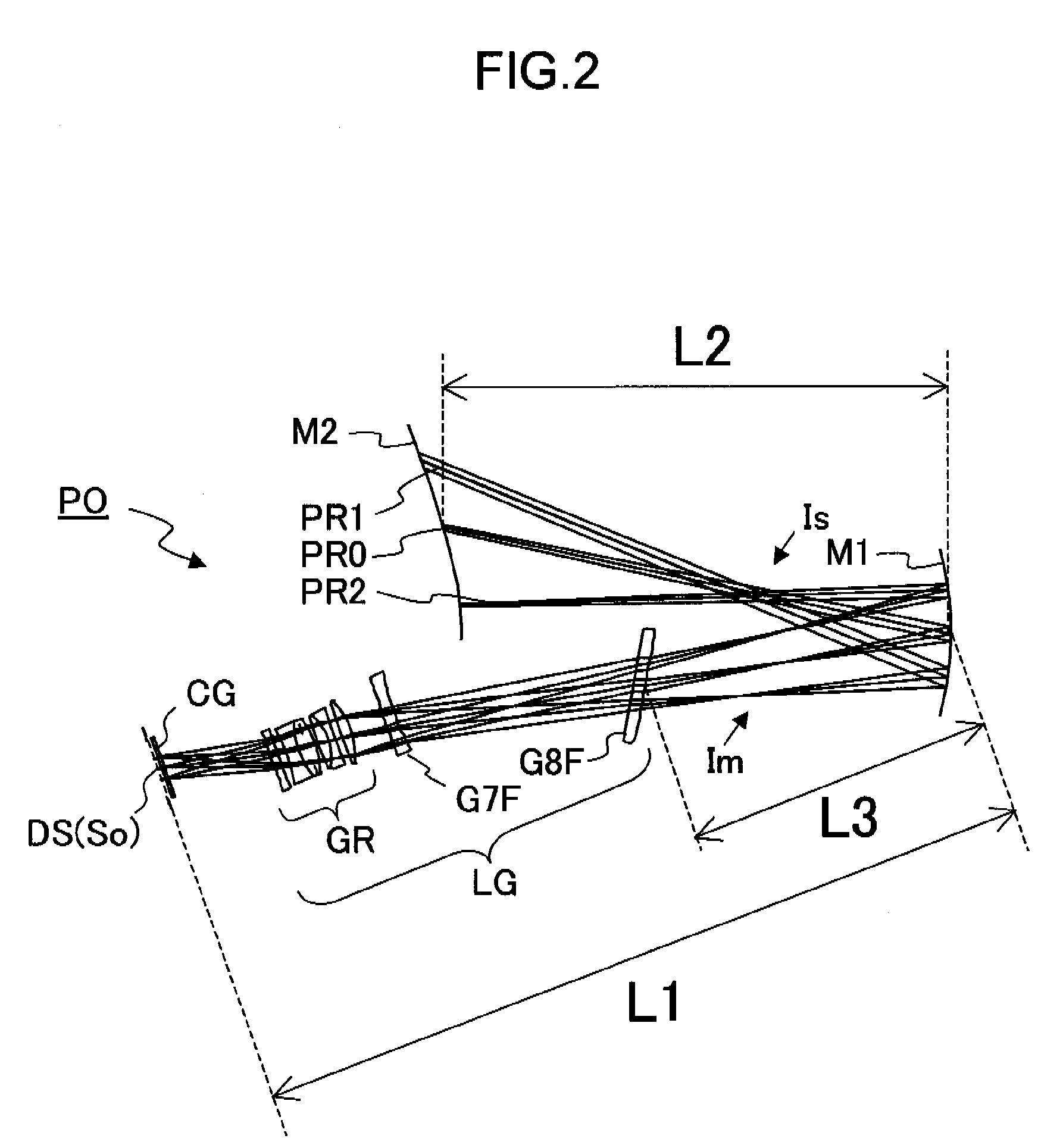
An oblique projection optical system enlarges an image formed on a display device surface, and obliquely projects the enlarged image on a screen surface. The oblique projection optical system has, in the order from a reduction side: a refraction optical portion having a positive optical power, a concave reflection surface having a positive optical power, and a convex reflection surface having a negative optical power. The refraction optical portion includes a rotationally symmetric coaxial refraction group. An intermediate image of the image formed on the display device surface is formed between the refraction optical portion and the concave reflection surface. An aperture stop image is formed between the concave reflection surface and the convex reflection surface. The concave reflection surface and the convex reflection surface fulfill prescribed conditional formulae.

Description

[0001]This application is based on Japanese Patent Application No. 2007-337261 filed on Dec. 27, 2007, the contents of which are hereby incorporated by reference.BACKGROUND OF THE INVENTION[0002]1. Field of the Invention[0003]The present invention relates to an oblique projection optical system, for example, to an oblique projection optical system that is incorporated in an image projection apparatus, which has a display device such as a digital micromirror device and a liquid crystal display device, enlarges an image formed on a display device surface and obliquely projects it on a screen surface.[0004]2. Description of Related Art[0005]In recent years, the demand for wide-angle projection in a projector is increasing. And not only in use of rear projection but also in use of front projection, wide-angle projectors that use mirrors in a projection optical system have been developed one after another. Using mirrors in a projection optical system makes it possible to achieve wide-ang...

Claims


Application Information

Patent Timeline
Patent Type & Authority Applications(United States)
IPC IPC(8): G03B21/28
CPCG02B13/16G03B21/28G02B17/0852G02B17/0816
Inventor IMAOKA, MASAYUKIYAMADA, KEIKO
Owner KONICA MINOLTA OPTO
Why Eureka
Try Eureka