Lens control apparatus, lens barrel, imaging apparatus, and optical apparatus

a control apparatus and lens technology, applied in the field of lenses control apparatus, can solve the problems of significant change in the physical and size of the retaining member made of plastic material, possible thermal expansion of the component member possible deformation of the lens unit, so as to reduce the phenomenon of defocusing of the focus lens and small in size

Inactive Publication Date: 2009-07-02
CANON KK
View PDF4 Cites 13 Cited by
  • Summary
  • Abstract
  • Description
  • Claims
  • Application Information

AI Technical Summary

Benefits of technology

[0017]The present invention is directed to a lens control apparatus, a lens barrel, an imaging apparatus, and an optical apparatus, which are small in size and capable of reducing a phenomenon of defocusing of a focus lens that may occur when the temperature of and around the focus lens becomes high.

Problems solved by technology

On the other hand, in this case, a problem may arise in that the physical property and size of the retaining member made of a plastic material significantly change due to a high sensitivity to the change of temperature or moisture.
In this case, the optical performance may degrade due to a phenomenon of defocusing that may arise due to the change in the focal length and in-focus position.
The most significant cause for such defocusing is a possible thermal expansion of the component member for a lens unit occurring due to the temperature rise.
Accordingly, in this case, the entire mechanical length of the lens barrel may become long and the size thereof may become large.

Method used


Image

  • Lens control apparatus, lens barrel, imaging apparatus, and optical apparatus
  • Lens control apparatus, lens barrel, imaging apparatus, and optical apparatus
  • Lens control apparatus, lens barrel, imaging apparatus, and optical apparatus

Examples


first exemplary embodiment

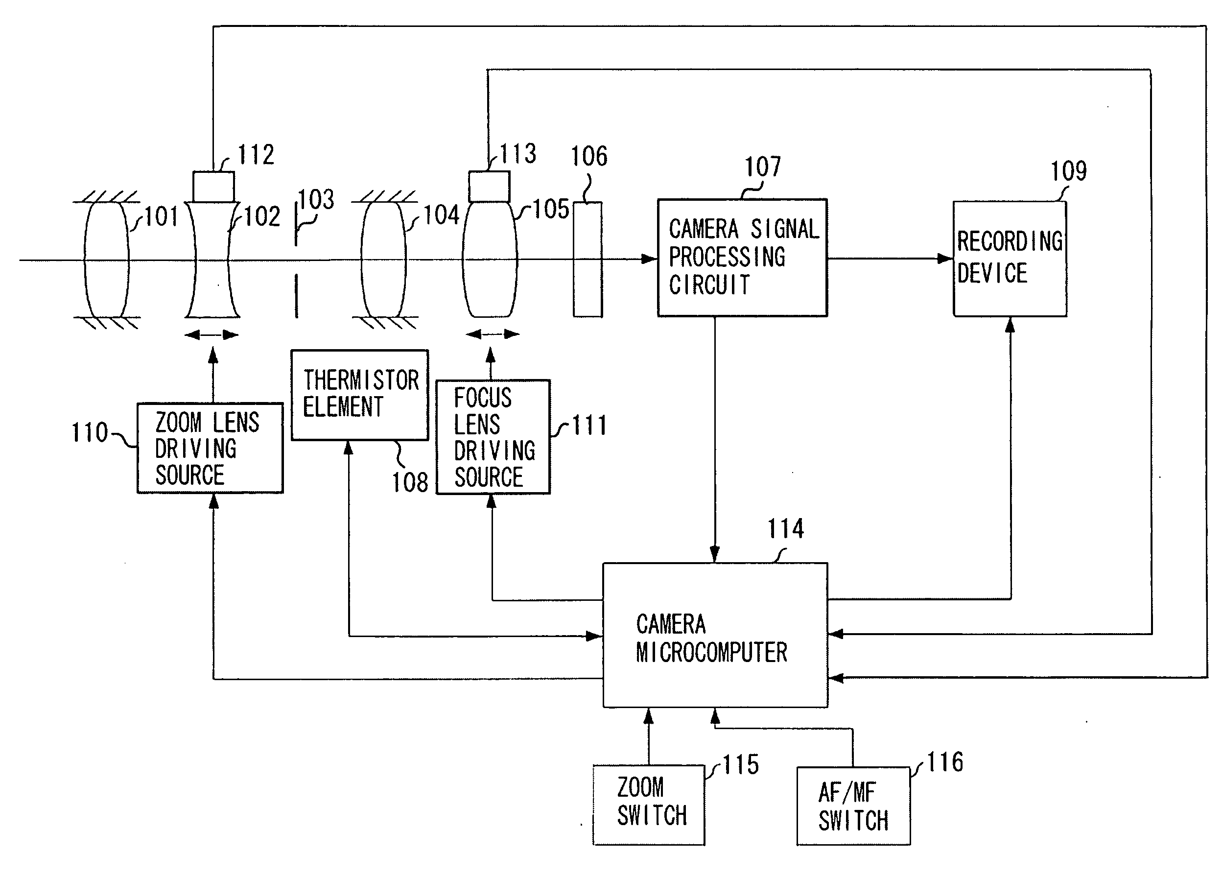
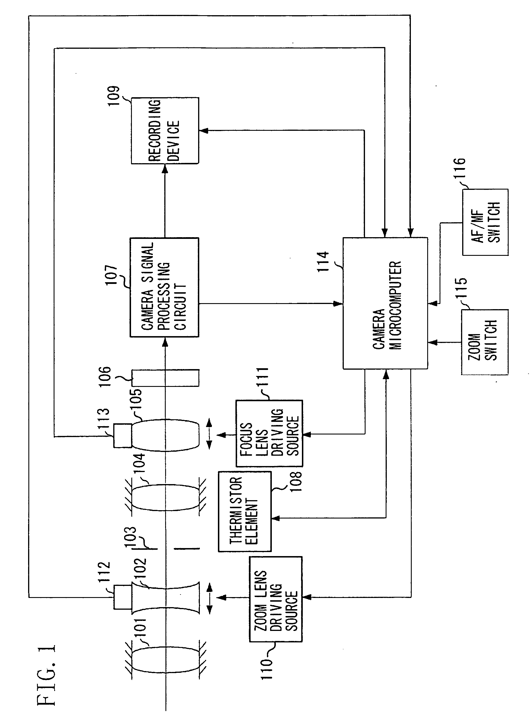
[0030]A first exemplary embodiment of the present invention will now be described below. FIG. 1 illustrates an example of a system configuration of an imaging apparatus, such as a video camera, including a lens control apparatus according to the first exemplary embodiment of the present invention. Note that a plastic material is used as a material of a retaining member for a lens barrel and an optical system.

[0031]Referring to FIG. 1, the imaging apparatus includes a first stationary lens unit 101, a zoom lens 102, which is a lens unit for varying magnification, a diaphragm 103, and a second stationary lens unit 104. A focus lens 105 is a lens unit having a focusing function and a compensation function for compensating for the displacement of a focal plane caused by variation of magnification.

[0032]A zoom lens driving source 110 drives the zoom lens 102. A focus lens driving source 111 drives the focus lens 105. Each of the zoom lens driving source 110 and the focus lens driving sou...

second exemplary embodiment

[0082]A second exemplary embodiment of the present invention will be described below. In the case where a stepping motor is used to drive the zoom lens 102, the zoom lens 102 cannot always be stopped at a desired zoom lens position due to hysteresis or a stopping accuracy (the resolution of the stepping motor) for stopping the zoom lens 102.

[0083]In particular, in the vicinity of the telephoto end position, in which the moving amount for moving the focus lens 105 is larger than the moving amount for moving the zoom lens 102, the focus lens 105 may be defocused. In this case, a phenomenon of small blur may occur in the captured image. In this regard, the present exemplary embodiment can immediately drive the focus lens 105 to an in-focus position in the case of the AF mode even if a phenomenon of small blur has occurred due to the above-described causes. However, in the case of the MF mode, the above-described problem cannot be easily solved. In the second exemplary embodiment of the...

third exemplary embodiment

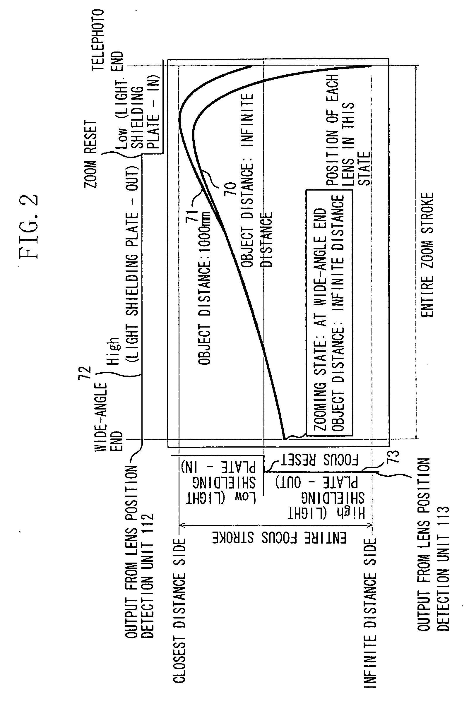
[0106]A third exemplary embodiment of the present invention will be described below. FIG. 7 illustrates an exemplary position of each of the zoom lens 102 and the focus lens 105 when the zoom lens 102 and the focus lens 105 are controlled along the cam locus. In the example illustrated in FIG. 7, the horizontal axis indicates a position of the zoom lens 102 between the wide-angle end and the telephoto end. The vertical axis indicates a position of the focus lens 105 between the infinite distance and the close distance.

[0107]Referring to FIG. 7, a curve 770 indicates control positions for the zoom lens 102 and the focus lens 105 at an infinite object distance. A curve 771 indicates control positions for the zoom lens 102 and the focus lens 105 in the case where the object distance is at 1,000 mm.

[0108]An output 772 from the lens position detection unit 112 is changed according to a state (“in” (“high”) state or “out” (“low”) state) of a light-shielding plate (not illustrated) of the ...


PUM


Abstract

A lens control apparatus includes a temperature detection unit configured to detect a temperature near a zoom lens and a focus lens, a zoom lens drive unit configured to drive the zoom lens, and a controller configured, if it is determined that a current temperature near the zoom lens and the focus lens detected by the temperature detection unit is higher than a reference temperature, to acquire a telephoto end position to be set at the current temperature, to compare the telephoto end position with a current position of the zoom lens, and to cause the zoom lens drive unit to move the zoom lens to the telephoto end position if the current position of the zoom lens is located beyond the telephoto end position on a telephoto side.

Description

BACKGROUND OF THE INVENTION[0001]1. Field of the Invention[0002]The present invention relates to a lens control apparatus configured to control the position of a zoom lens and a focus lens, to a lens barrel, to an imaging apparatus having the lens barrel and the lens control apparatus, and to an optical apparatus.[0003]2. Description of the Related Art[0004]Conventionally, a lens barrel for a still camera or a video camera has been widely used that drives a zoom lens and a focus lens, each including a lens unit, with a driving member, such as a stepping motor.[0005]Generally, in the case of driving a lens unit with a driving member, such as a stepping motor, an open loop control method is often used as a control method for driving and positioning the lens unit. This is because in the open loop control method, it is not necessary to provide a detection device for detecting the current position of the lens unit. In addition, this is because in the open loop control method, the configu...

Claims


Application Information

Patent Timeline
Patent Type & Authority Applications(United States)
IPC IPC(8): G02B15/14
CPCG02B7/102G02B7/028
Inventor ISHIKAWA, DAISUKETOMOSADA, TOSHIHIKO
Owner CANON KK
Why Eureka
Try Eureka