Optical transmission device, optical transmission system, and bandwidth control method

a technology of optical transmission system and optical transmission device, which is applied in the direction of digital transmission, multi-channel communication, wavelength-division multiplex system, etc., can solve the problem of inability to transparently transfer client signals in intact form of physical layer data, affecting the smooth operation of the client device, and increasing the processing load of the counterpart client device. achieve the effect of transparent transfer of client data

Inactive Publication Date: 2009-07-02
FUJITSU LTD
View PDF5 Cites 10 Cited by
  • Summary
  • Abstract
  • Description
  • Claims
  • Application Information

AI Technical Summary

Benefits of technology

[0035]The invention has been devised in order to resolve the above-mentioned and other problems. An object of the invention is to provide an optical transmission device, an optical transmission system, a bandwidth control method, and a bandwidth control program for equilibrating a bandwidth of client data so as to avoid occurrence of frame discard on the destination client side, and thereby achieving transparent transfer of the client data.

Problems solved by technology

This causes a problem that when the optical network side frequency of the optical transmission device is higher than that of the client signal and hence the inter frame gap of the input signal reaches a minimum value having been set forth for each client device according to an 8B / 10B encoding system, the processing load increases in the counterpart client device so that frame discard occurs.
Then, the frame discard causes a problem that transparent transfer of a client signal in the intact form of physical layer data cannot be performed.
This causes a problem that transparent transfer of a client signal in the intact form of physical layer data cannot be performed.

Method used


Image

  • Optical transmission device, optical transmission system, and bandwidth control method
  • Optical transmission device, optical transmission system, and bandwidth control method
  • Optical transmission device, optical transmission system, and bandwidth control method

Examples


embodiment 1

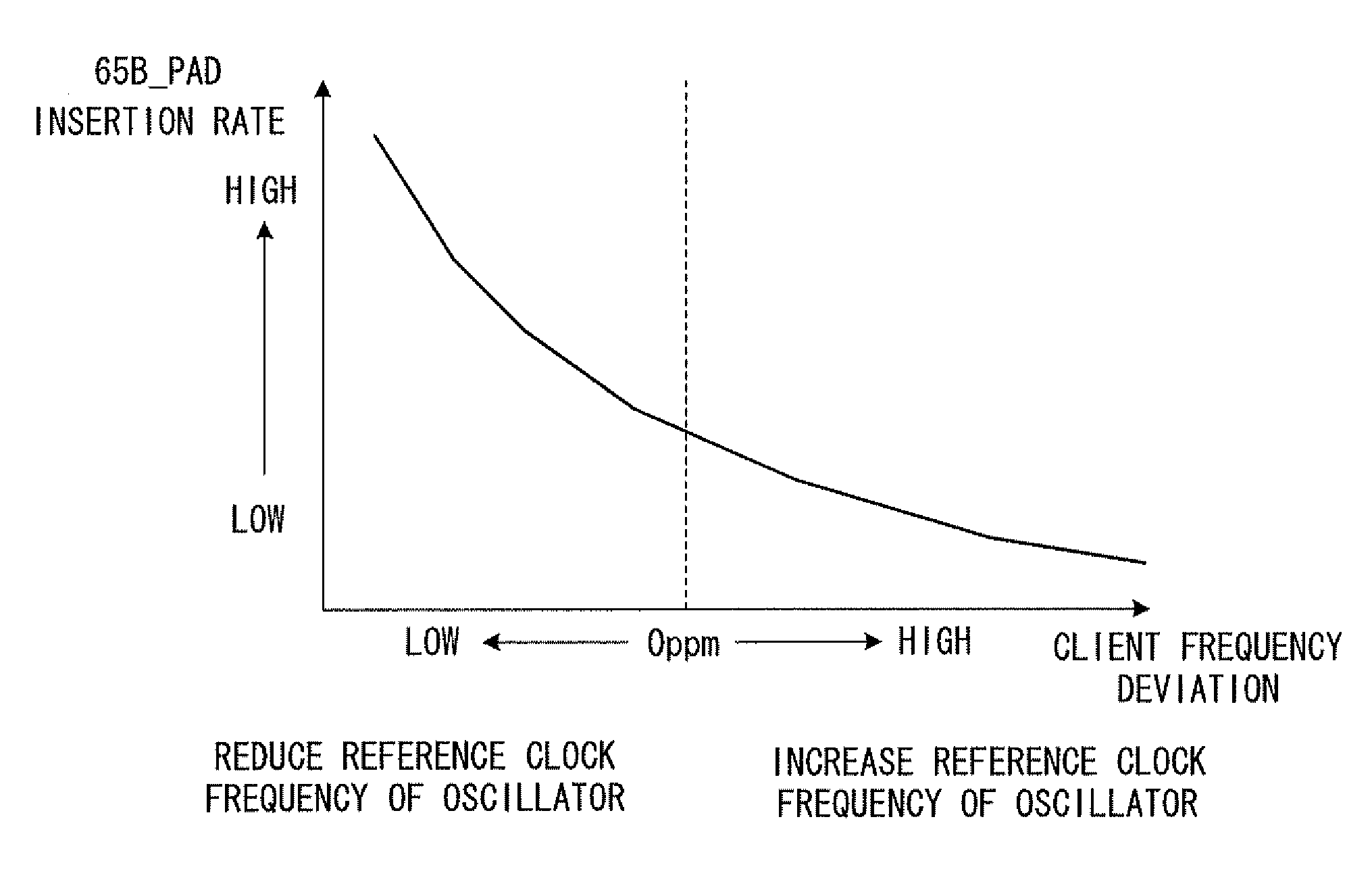
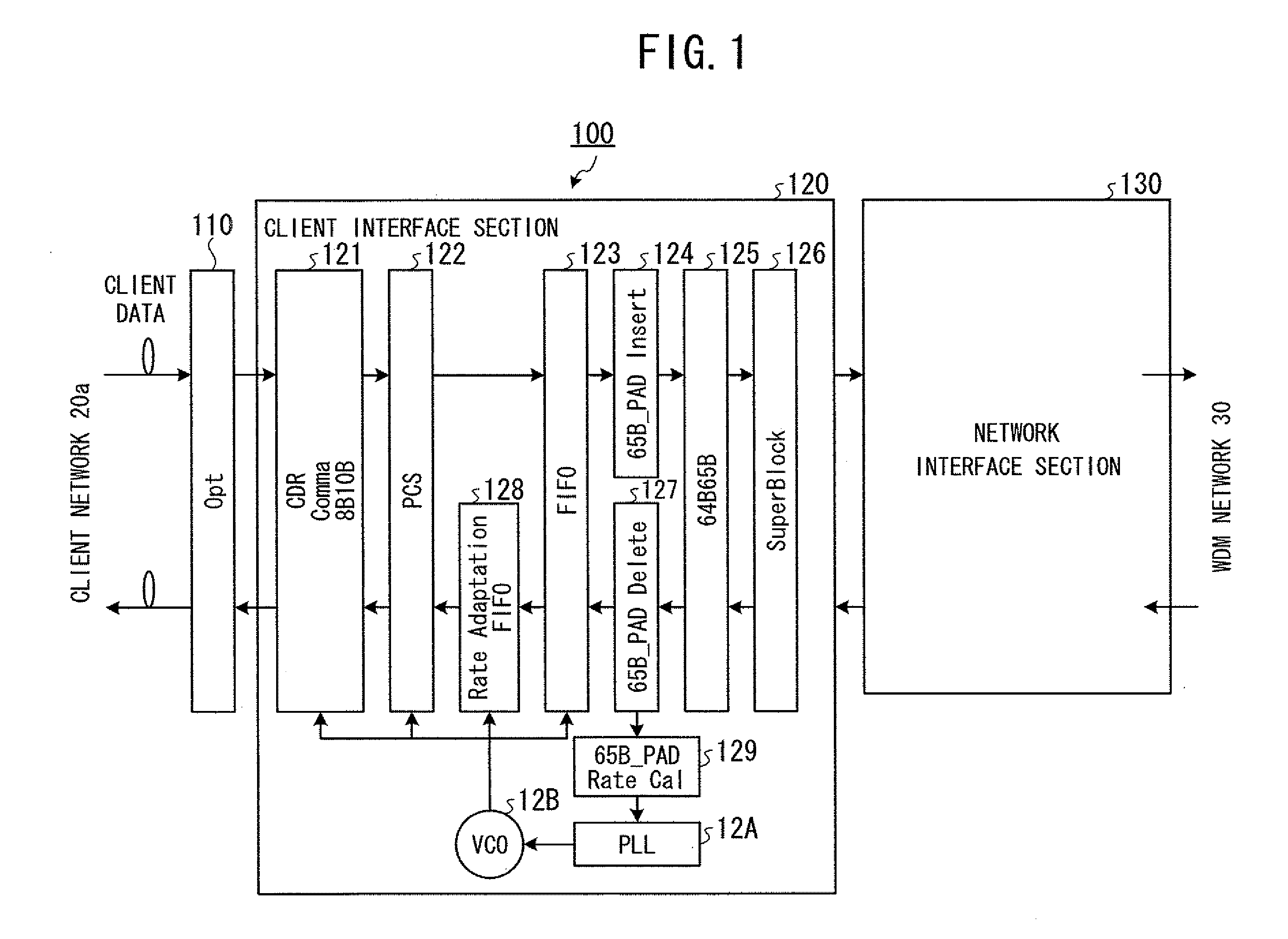
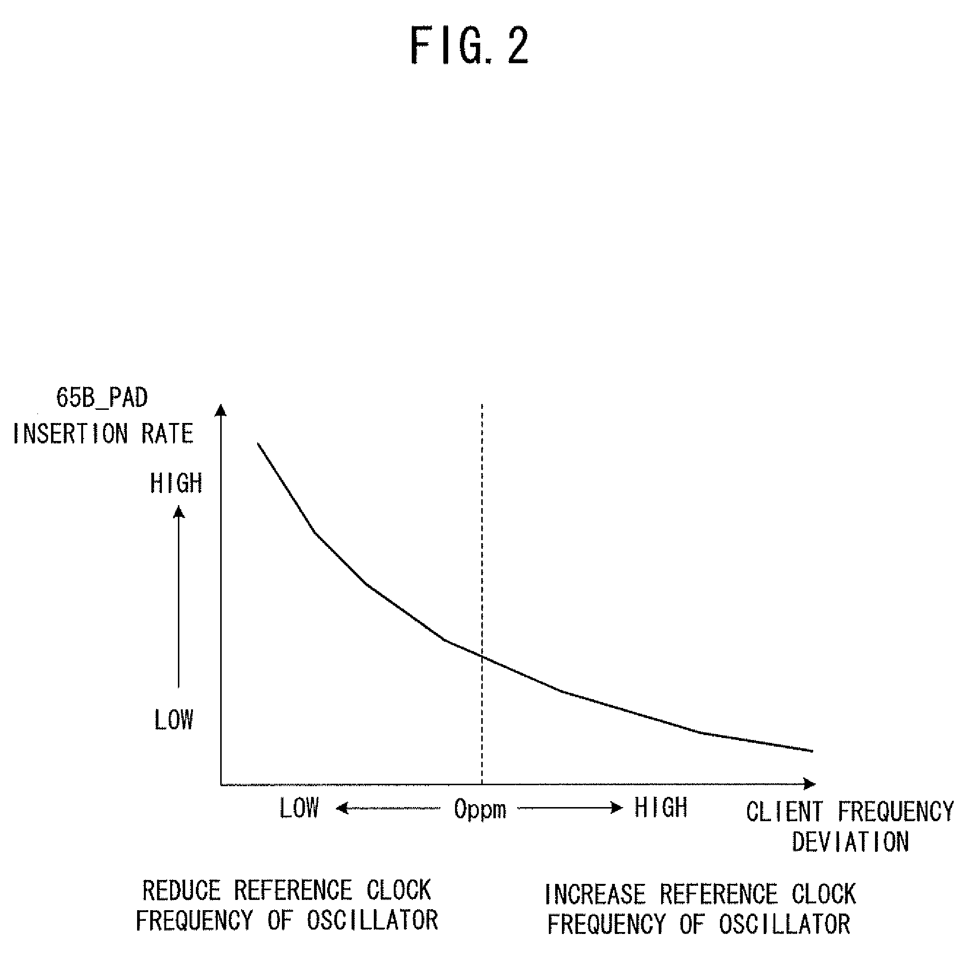
[0067]Then, in the WDM transmission device 100 the padding signal rate calculation section 129, the frequency synchronization control section 12A, and the voltage controlled oscillator 12B control the frequency of the clock used as a reference at the time of transmitting physical layer data from the WDM transmission device 100 to the client network 20a side, on the basis of the ratio of padding signals contained in the physical layer data.

[0068]In typical, the padding signal inserted into the physical layer data is treated as redundant data to be discarded in the counterpart WDM transmission device. However, in the Embodiment 1, the padding signal is utilized so that bandwidth control is realized at the time of transmitting physical layer data.

[0069]The individual functional sections are described below in detail.

[0070]The data extraction section 121 is a processing section for extracting a clock signal and a data signal from physical layer data transmitted from the client network ...

embodiment 2

[0113]Then, in the Embodiment 2, in this WDM transmission device 200, the memory buffer section 22C and the inter frame gap equalization processing section 22D perform inter frame gap equalization on the physical layer data transmitted from the client network 20a side to the WDM network 30 side, while the inter frame gap equalization processing section 22E performs inter frame gap equalization on the physical layer data transmitted from the WDM network 30 side to the client side.

[0114]The individual functional sections are described below in detail.

[0115]The memory buffer section 22C is a buffer for storing all of frames and inter frame gaps in the physical layer data sent from the data extraction section 121.

[0116]The inter frame gap equalization processing section 22D is a processing section for equalizing inter frame gaps in the physical layer data stored in the memory buffer section 22C. FIG. 5 is a diagram showing equalization for inter frame gaps performed by an inter frame ga...

embodiment 3

[0147]Then, in the Embodiment 3, in this WDM transmission device 300, the idle code counter section 32F and the idle code optimization section 32H perform inter frame gap equilibration on the physical layer data transmitted from the client network 20a side to the WDM network 30 side, while the idle code counter section 32G and the idle code optimization section 32I perform inter frame gap equilibration on the physical layer data transmitted from the WDM network 30 side to the client side.

[0148]The individual functional sections are described below in detail.

[0149]The idle code counter section 32F is a processing section for counting the number of idle codes contained in the inter frame gaps in the physical layer data stored in the memory buffer section 22C.

[0150]The idle code counter section 32F is a processing section for counting the number of idle codes contained in the physical layer data stored in the rate adaptation FIFO of the rate adaptation section 128.

[0151]The idle code o...


PUM


Abstract

A system and method of transmitting client data encoded according to an 8B/10B encoding between a client side and an optical communication network side, including inserting padding signals in an amount corresponding to a rate difference between a clock on the client side and a clock in the optical transmission device and controlling a clock to be used as a reference in transmitting the client data to synchronize with a clock having been used as a reference in transmitting the client data on the basis of a ratio of padding signals having been inserted in the client data.

Description

CROSS-REFERENCE TO RELATED APPLICATIONS[0001]This application is based upon and claims the benefit of priority of the prior Japanese Application No. 2007-296044, filed on Nov. 14, 2007, the entire contents of which are incorporated herein by reference.BACKGROUND[0002]1. Field[0003]The invention relates to an optical transmission device, an optical transmission system, and a bandwidth control method for transmitting client data encoded according to an 8B / 10B encoding system, between a client side and an optical communication network side. In particular, the invention relates to an optical transmission device, an optical transmission system, and a bandwidth control method for equilibrating the bandwidth of client data and thereby avoiding an occurrence of frame discard on the destination client side, and transferring the client data transparently.[0004]2. Description of the Related Art[0005]In recent years, in optical transmission systems employing optical communication networks, opti...

Claims


Application Information

Patent Timeline
Patent Type & Authority Applications(United States)
IPC IPC(8): H04B10/00H04J3/00
CPCH04J3/07H04L25/4908H04J14/02H04J3/1617
Inventor NONAKA, AYUMUSHIMADA, YUJIKURODA, HIDEONEKODA, KOJI
Owner FUJITSU LTD
Why Eureka
Try Eureka