Vacuum vapor desposition apparatus

a vacuum vapor and desposition apparatus technology, applied in vacuum evaporation coatings, brushes, coatings, etc., to achieve the effect of preventing unevenness, uniform film thickness distribution of workpieces, and convenient handling

Inactive Publication Date: 2009-07-02
SATO KEIICHI +4
View PDF14 Cites 2 Cited by
  • Summary
  • Abstract
  • Description
  • Claims
  • Application Information

AI Technical Summary

Benefits of technology

[0029]In the vacuum vapor deposition apparatus of the first and second aspects of the present invention, the crucible is comprised of a monolithic structure extending over the entire area of the vaporizing chamber and has at least one groove in the upper surface thereof. The at least one groove has a length from one end of the upper surface of the crucible to the other end thereof and serves as a portion for containing the evaporation material. Accordingly, the heating surface area (area where the crucible is in contact with the evaporation material) of the crucible becomes large. Thus, a desired vaporized amount of the evaporation material can be obtained without heating the hot walls to higher temperature, arranging a larger number of crucibles, and the like. Further, since the crucible is a monolithic structure, even if there are differences in temperature among positions in the hot walls, temperature is uniform over the entire crucible due to heat conduction in portions (mound portions) of the upper surface of the crucible where the at least one groove is not formed and portions under the at least one groove. Accordingly, it is possible to prevent unevenness in the vaporization of the evaporation material and to make the film thickness distribution of the workpiece uniform. Moreover, a small amount of the evaporation material can also be easily dealt with by appropriately setting the number and dimensions (width, depth, and the like) of the at least one groove. Accordingly, an increase in the size of a to-be-coated region of the workpiece, a small amount of the evaporation material, and the like can be easily dealt with at low cost without heating the hot walls to a higher temperature, arranging a larger number of crucibles, and the like. Thus, the cost of the apparatus can also be reduced.
[0038]According to the method of the twelfth aspect of the present invention, which is a method of manufacturing a thin film of an organic electroluminescence element, in the vacuum vapor deposition apparatus of any one of the fifth and ninth aspects of the present invention, an organic material is used as the evaporation material. Further, the crucible of the vacuum vapor deposition apparatus is divided into a plurality of regions. Temperatures are measured for the respective regions, and outputs of the heating means such as heaters are individually controlled based on the measured temperatures of the respective regions so that the temperatures of the respective regions become constant. Accordingly, for each region, the temperature of the crucible is controlled and the temperature of the evaporation material is controlled. Thus, it is possible to more reliably prevent unevenness in the vaporization of the evaporation material in the longitudinal direction. Consequently, it is possible to more reliably deal with an increase in the size of a to-be-coated region of the workpiece, a small amount of the evaporation material, and the like.

Problems solved by technology

(1) The heating surface area of one known crucible 1 or 3, i.e., the area thereof which is in contact with the evaporation material 2, is small. Accordingly, in order to obtain a desired vaporized amount of the evaporation material 2, it is necessary to heat the hot walls 5 to a higher temperature by increasing the capacities of electric heaters or to arrange a larger number of crucibles 1 or 3. Thus, there arise problems such as an increase in the size of an evaporation source, an increase in the effort of arranging the crucibles, and an increase in the cost of a system.
(2) If a plurality of crucibles 1 or 3 is arranged in a dispersed manner, unevenness in the vaporization of the evaporation material 2 is prone to occur. As a result, the film thickness distribution of a thin film formed on a substrate becomes non-uniform. Even if the temperature of the hot walls 5 is controlled using electric heaters, there are cases where a difference occurs between, for example, temperature (e.g., 350° C.) at part P of the hot wall 5 and temperature (e.g., 300° C.) at part Q thereof as illustrated in FIGS. 19A and 19B. In this case, the evaporation material 2 in the crucible 1 or 3 on the front side mainly receives radiant heat T from part P to vaporize, and the evaporation material 2 in the crucible 1 or 3 on the back side mainly receives radiant heat T from part Q to vaporize. Accordingly, there occurs unevenness (difference) in the vaporized amount of the evaporation material 2 between the crucible 1 or 3 on the front side and the crucible 1 or 3 on the back side. Thus, in order to cope with this, it is necessary to arrange a large number of crucibles 1 or 3 at smaller intervals by decreasing the sizes of the crucibles 1 or 3. In this case, there also arise problems such as an increase in the effort of arranging the crucibles and an increase in the cost of a system. In particular, in vacuum vapor deposition apparatus for organic EL, such problems are prone to occur because the sizes of to-be-coated regions have increased with an increase in the sizes of FPD substrates.
(3) In the case where a small amount of the evaporation material 2 is vaporized, i.e., in the case where the evaporation material2 of which amount is originally small is vaporized or where the amount of the evaporation material 2 decreases due to vaporization to become small, it makes a distance between the periphery portion of the evaporation material 2 where vaporization proceeds relatively quickly and the inner surfaces of the crucibles 1 or 3, and the efficiency of heat conduction from the crucibles 1 or 3 to the evaporation material 2 becomes low. Thus, unevenness in the vaporized amount of the evaporation material 2 among the crucibles 1 or 3 is prone to occur, and the distribution of a film thickness is prone to become non-uniform. Accordingly, in order to cope with this, it is also necessary to arrange a large number of crucibles 1 or 3. As a result, there arise problems such as an increase in the effort of arranging the crucibles and an increase in the cost of a system. In particular, in vacuum vapor deposition apparatus for organic EL, such problems are prone to occur, because a very thin film having a thickness of, for example, approximately 400 angstroms is formed and therefore the amounts of host and dopant materials, which are organic materials and used to form this film, are very small (e.g., approximately 2 g).

Method used


Image

  • Vacuum vapor desposition apparatus
  • Vacuum vapor desposition apparatus
  • Vacuum vapor desposition apparatus

Examples


first embodiment

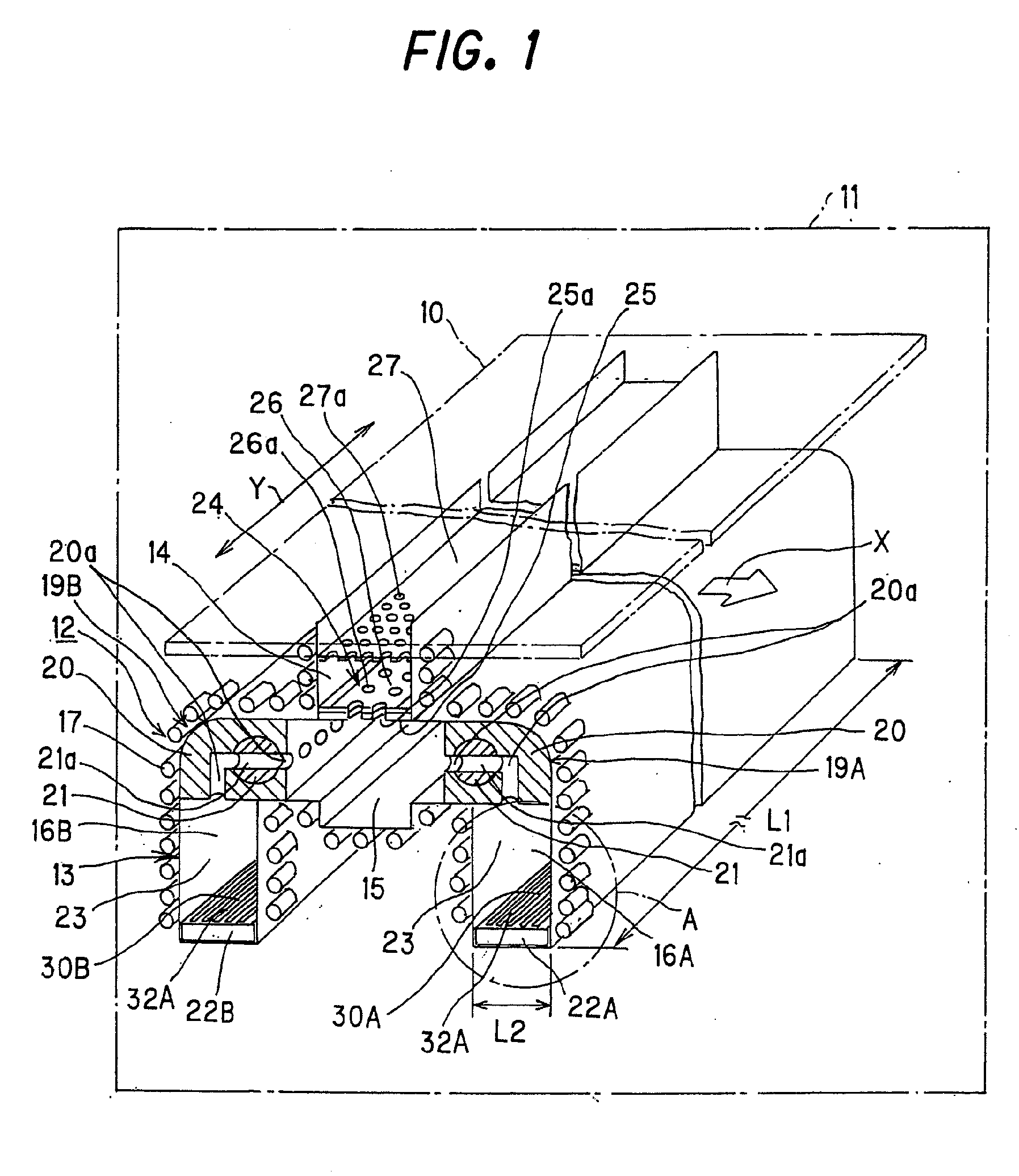
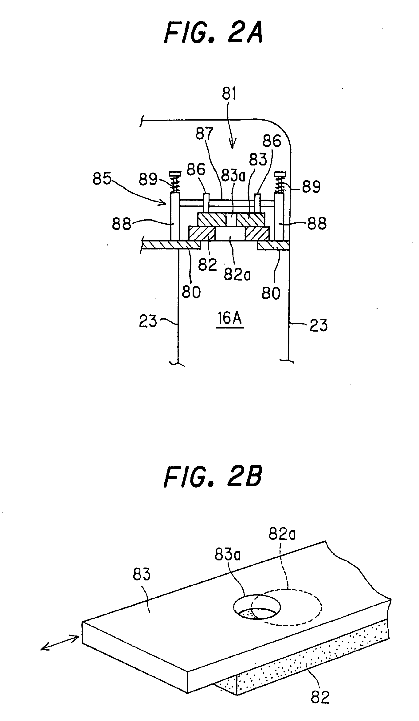
[0060]FIG. 1 is a perspective view illustrating the construction of a vacuum vapor deposition apparatus according to a first embodiment of the present invention. FIG. 3 is an enlarged perspective view of part A of FIG. 1. FIG. 4A is a cross-sectional view (plan view of a crucible) as seen from the direction of arrows B of FIG. 3. FIG. 4B is an enlarged cross-sectional view taken along the line C-C of FIG. 4A. It should be noted that FIGS. 2A and 2B are views illustrating another example of the construction of a spool shutter in the vacuum vapor deposition apparatus of the first embodiment.

[0061]As illustrated in FIG. 1, the vacuum vapor deposition apparatus of the first embodiment includes a main system 12 of an vapor deposition apparatus and a substrate transport system (not shown) in a vacuum chamber 11 and is intended for co-deposition and organic EL. The main system 12 serves as an evaporation source. The substrate transport system is provided above the main system 12.

[0062]The ...

second embodiment

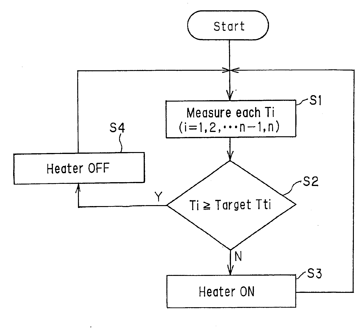
[0084]FIG. 7 is a perspective view illustrating the construction of an essential part of a vacuum vapor deposition apparatus according to a second embodiment of the present invention. FIG. 8 is a cross-sectional view (plan view of electric heaters) as seen from the direction of arrows D of FIG. 7. FIG. 9 is a flowchart for explaining temperature control.

[0085]In the vacuum vapor deposition apparatus of the second embodiment which is illustrated in FIGS. 7 and 8, electric heaters 41 are further provided as heating means in the crucible 22A for a dopant material in the vacuum vapor deposition apparatus of the first embodiment. Though not illustrated, the crucible 22B for a host material also has a construction in which electric heaters 41 are provided as in the crucible 22A. Except for the above, the construction (the overall construction and arrangement of the crucibles, the overall construction of the vacuum vapor deposition apparatus, and the like) of the vacuum vapor deposition ap...

third embodiment

[0092]FIG. 12 is a perspective view illustrating the construction of an essential part of a vacuum vapor deposition apparatus according to a third embodiment of the present invention. FIG. 13A is a cross-sectional view (plan view of a crucible) as seen from the direction of arrows E of FIG. 12. FIG. 13B is an enlarged cross-sectional view taken along the line F-F of FIG. 13A.

[0093]As illustrated in FIGS. 12 to 13B, in the vacuum vapor deposition apparatus of the third embodiment, instead of slit grooves, holes 51 are provided in the surface 31 of the crucible 22A for the dopant material in the vacuum vapor deposition apparatus of the aforementioned first embodiment. Although not shown, the crucible 22B for the host material also has a construction in which holes 51 are provided as in the crucible 22A. Except for the above, the construction (the arrangement of the crucibles, the overall construction of the vacuum vapor deposition apparatus, and the like) of the vacuum vapor depositio...


PUM

PropertyMeasurementUnit
diameteraaaaaaaaaa
temperatureaaaaaaaaaa
thicknessaaaaaaaaaa

Abstract

A crucible is a monolithic structure extending over an entire area of a vaporizing chamber and has at least one slit groove provided in the upper surface thereof. The at least one slit groove has a length from one end of the upper surface of the crucible to other end thereof. The at least one slit groove is used as a portion for containing the evaporation material (dopant material or the like). Alternatively, a crucible is a monolithic structure extending over the entire area of the vaporizing chamber and has a plurality of holes provided in the upper surface thereof. The holes are used as portions for containing the evaporation material. Further, the crucible is divided into a plurality of regions, and individual electric heaters are provided under the lower surface of the crucible for the respective regions, whereby temperature can be individually controlled for the respective regions by the electric heaters.

Description

CROSS REFERENCE TO RELATED APPLICATIONS[0001]This application is a Divisional of co-pending application Ser. No. 11 / 334,409 filed on Jan. 19, 2006, and for which priority is claimed under 35 U.S.C. § 120; and this application claims priority of Application No. 2005-013673 filed in Japan on Jan. 21, 2005 and Application No. 2005-355652 filed in Japan on Dec. 9, 2005 under 35 U.S.C. § 119; the entire contents of all are hereby incorporated by reference.BACKGROUND OF THE INVENTION[0002]1. Field of the Invention[0003]The present invention relates to a vacuum vapor deposition apparatus which evaporates and deposits an evaporation material such as an organic material on a surface of a workpiece such as a substrate for a flat panel display to form a thin film.[0004]2. Description of the Related Art[0005]In a vacuum vapor deposition apparatus, an evaporation material is contained in a crucible provided in a vaporizing chamber, and this evaporation material is heated by radiant heat from sid...

Claims


Application Information

Patent Timeline
Patent Type & Authority Applications(United States)
IPC IPC(8): C23C16/52
CPCC23C14/543C23C14/243A46B17/02A46B2200/1066
Inventor SATO, KEIICHIKOBAYASHI, TOSHIROKATO, MITSUOKAMIKAWA, SUSUMUWADA, KOUZUO
Owner SATO KEIICHI
Why Eureka
Try Eureka