
Software defined radio with configurable multi-band front-end

a software defined radio and front-end technology, applied in the direction of transmission, electrical equipment, etc., can solve the problems of not being being considered impractical to be able to support all, and having carrier disadvantages,

Inactive Publication Date: 2009-07-02
LOGUS BROADBRAND WIRELESS SOLUTIONS INC
View PDF9 Cites 50 Cited by
  • Summary
  • Abstract
  • Description
  • Claims
  • Application Information

AI Technical Summary

Benefits of technology

[0006]It is an object of the present invention to provide a multi-band enabled software defined radio platform to obviate or mitigate at least some of the above-presented disadvantages.

Problems solved by technology

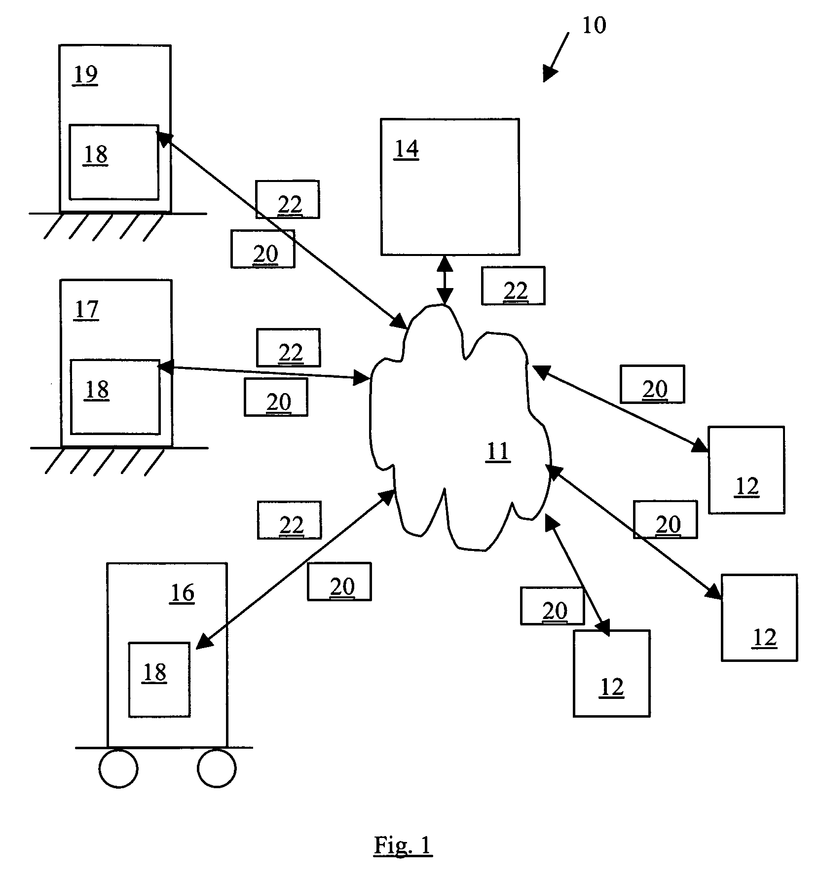
Contemporary telecommunications technologies are unfortunately manufactured to be carrier, IF (intermediate frequency) and RF (Radio Frequency) bandwidth dependent, such as CDMA (code-division multiple access) and GSM (global system for mobile) that serve most of today's cell phones as well as other less portable wireless radios.
Further, even some of today's SDR (software defined radio) radios also have these unfortunate dependencies.
The disadvantage of having carrier, IF and RF bandwidth dependent configured wireless devices has been compounded in recent years due in part to advances in digital signal processing capabilities and in part to more and more traditional analog radio spectrum being freed for digital transmission (i.e. an increase in the wireless spectrum available to the carriers).
However, in view of the availability of global frequency spectrum, it is considered impractical to be able to support all variations for carrier, IF, and RF bandwidth dependencies within a single wireless device.
Therefore, connectivity is major issue for wireless devices, as all radios need to have both an over-the-air interface at the radio signal frequency, and also at the base-band interface.

Method used


Image

  • Software defined radio with configurable multi-band front-end
  • Software defined radio with configurable multi-band front-end
  • Software defined radio with configurable multi-band front-end

Examples


example filter

Component 200 Configuration

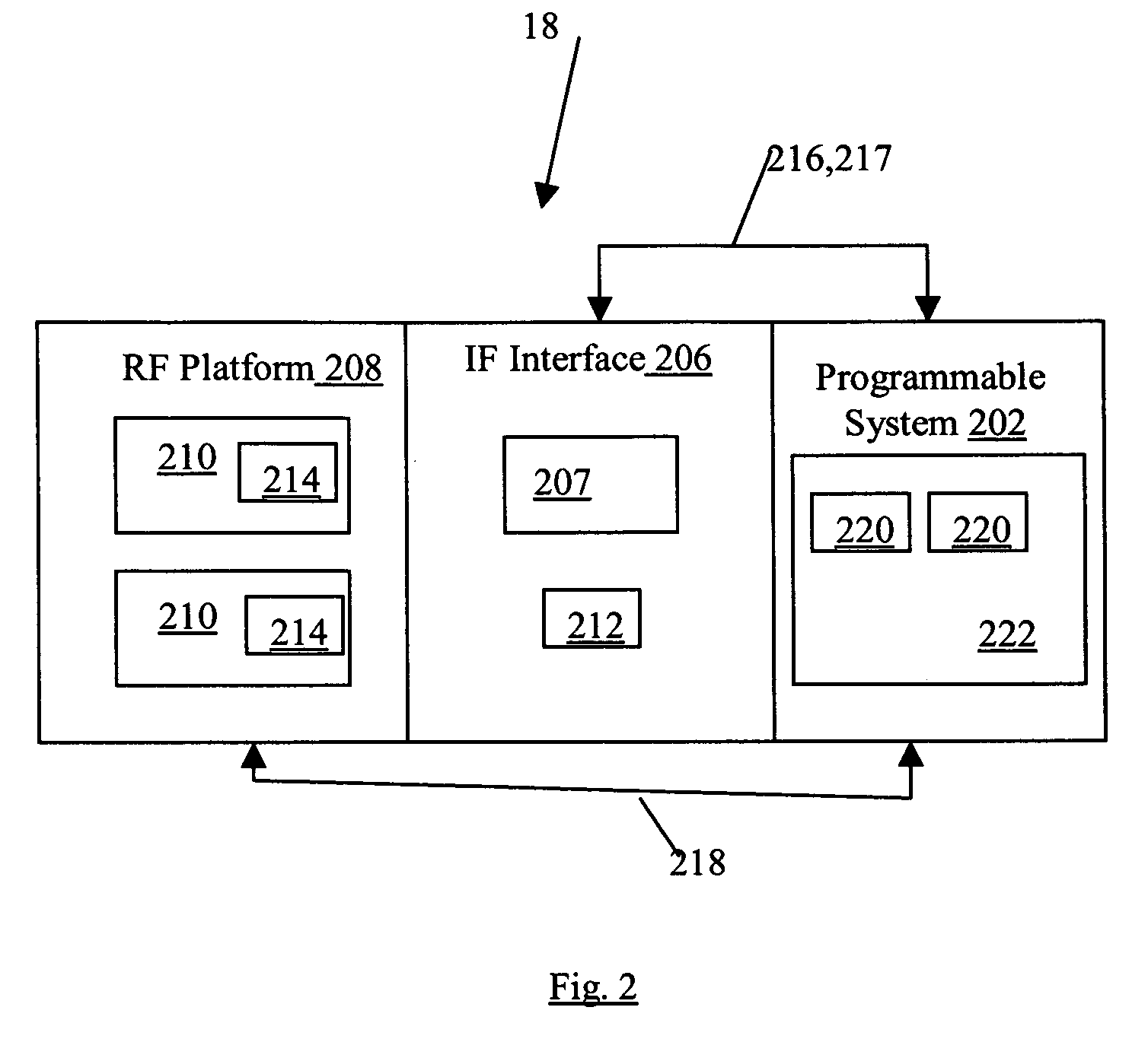
[0066]Referring to FIGS. 3, 5, 6, at high frequencies, reliable and effective RF-RF and IF-IF connections can be an engineering challenge. Reflection at the mating surfaces between the modular filter components 200 and the plafform / interface 208, 206 can severely attenuate the signals (both RF signal 20a version and the intermediate frequency signal 20a version) if connections between the RF platform 208 and the RF filters 212 and the IF interface 206 and the IF filters 214 are not matched properly for the signals 20a. In order to mitigate this issue, RF connectors 250, e.g. e.g. MMCX type, are employed for the mating of the plug-in filter component 200 and a main board 252 (e.g. PCB). The plug-in filter components 200 can have the same footprint and pin-outs 254 for IF 212 and RF 214 filters, or can have a different footprint, as desired. Further, the plug-in filter components 200 can have an intelligent unit 256 (e.g. memory and / or a processor) that is c...

example radio modules 210

Example Radio Modules 210

[0071]Referring to FIGS. 9A, 9B, 9C, 9D, the multi-band SDR 18 can consist of a plurality of different radio portions 210. Four example types of radio portions 210 can be selected as RF center frequency bands 234 of: 700 MHz; 2.5 GHz; 3.5 GHz; and 5.8 GHz with correspondingly configured sub-bands 236 via the plug-in RF filter modules 214, as shown by example. It is recognised that the RF filter modules 214 can have the center frequency band 234 and sub-bands 232 other than as shown, such as but not limited to further examples given in Appendix C. Further, it is recognised that the RF platform 208 can contain a plurality of radio portions 210 having the center frequency bands 234 and / or sub-bands 232 as configured via the plug-in filter modules 214 that are mounted on the corresponding mounting interface (e.g. board 252 and / or RF connections 250—see FIG. 6) of the radio portions 210.

[0072]Each radio portion 210 circuitry has a common architecture to facilitat...

example if interface 206

Example IF Interface 206

Receiver Portion 240

[0076]Referring to FIGS. 10A, 10B, 10C, the IF interface 206 is composed of a receiver portion 240 for providing corresponding downconversion processes 274 for the incoming analog signal 20a from the radio portions 210 of the RF platform 208 (see FIGS. 3 and 9A, 9B, 9C, 9D). The downconverted signal 20a is then processed by the plug-in filter modules 212 and then sent via the RX path to the ADC system 270 (see FIG. 12). It is recognised that a variety of component operations of the IF interface 206 for the receiver portion 240 (shown by example in FIG. 10A) can be monitored / controlled via the digital interface 216, 217 which is connected to the programmable system 208 (see FIG. 13).

[0077]Further, it is recognised that the receiver portion 240 may have more that one filter module 212 for accommodating the band pass filtering needs for different ones of the radio portions 210. As well, these plurality of filter modules 212 can be used to fac...


PUM


Abstract

A software defined radio (SDR) for communicating a plurality of radio signals over a wireless communications network. The radio comprising: a programmable system having a plurality of digital processors for processing digital data representing a digital form of the plurality of radio signals, the programmable system also for configuring operation of radio hardware for processing of the radio signals themselves; a configurable intermediate frequency (IF) interface for processing the plurality of radio signals for subsequent processing as the digital data communicated to the programmable system and the digital data received from the programmable system, the IF interface having a first connector for releasably connecting a modular IF filter component for use in the processing of said plurality of radio signals, the modular IF filter component being part of the radio hardware for selecting an IF center frequency and channel bandwidth of the SDR; and an RF platform coupled to the IF interface and configured for having with at least one radio portion, each radio portion for receiving and transmitting the radio signal over the communications network on behalf of the IF interface, said each radio portion having a second connector for releasably connecting a modular RF filter component for use in the processing of said plurality of radio signals, the modular RF filter component being part of the radio hardware for selecting an RF sub-band and RF center frequency of said each radio module; wherein the programmable system is adapted to configure operation of the SDR through recognition of the corresponding connected modular RF and IF filters.

Description

FIELD OF THE INVENTION[0001]This invention relates to processing of communicated radio signals using a combination of software and hardware components.BACKGROUND OF THE INVENTION[0002]Contemporary telecommunications technologies are unfortunately manufactured to be carrier, IF (intermediate frequency) and RF (Radio Frequency) bandwidth dependent, such as CDMA (code-division multiple access) and GSM (global system for mobile) that serve most of today's cell phones as well as other less portable wireless radios. Further, even some of today's SDR (software defined radio) radios also have these unfortunate dependencies. These dependencies necessitate radio and cell phone manufacturers (i.e. wireless device manufacturers) to manufacture a variety of different wireless devices for each carrier, IF, and bandwidth combination. These device varieties can exist for multiple carriers within a particular country, as well as for different carriers in different countries, in view of the multitude...

Claims


Application Information

Patent Timeline
Patent Type & Authority Applications(United States)
IPC IPC(8): H04B1/38
CPCH04B1/0039
Inventor RETNASOTHIE, FRANCIS EMMANUELOZDEMIR, MEHMET KEMAL
Owner LOGUS BROADBRAND WIRELESS SOLUTIONS INC
Learn More