Decoding apparatus and decoding method

Inactive Publication Date: 2009-07-02
RENESAS ELECTRONICS CORP
View PDF7 Cites 9 Cited by
  • Summary
  • Abstract
  • Description
  • Claims
  • Application Information

AI Technical Summary

Benefits of technology

[0019]The decoding apparatus and the decoding method according to t

Problems solved by technology

However, the present inventors have found a problem that, although the Viterbi decoding method taught by Iwata et al. performs additional traceback on a different path when a decoding result obtain

Method used


Image

  • Decoding apparatus and decoding method
  • Decoding apparatus and decoding method
  • Decoding apparatus and decoding method

Examples


Example

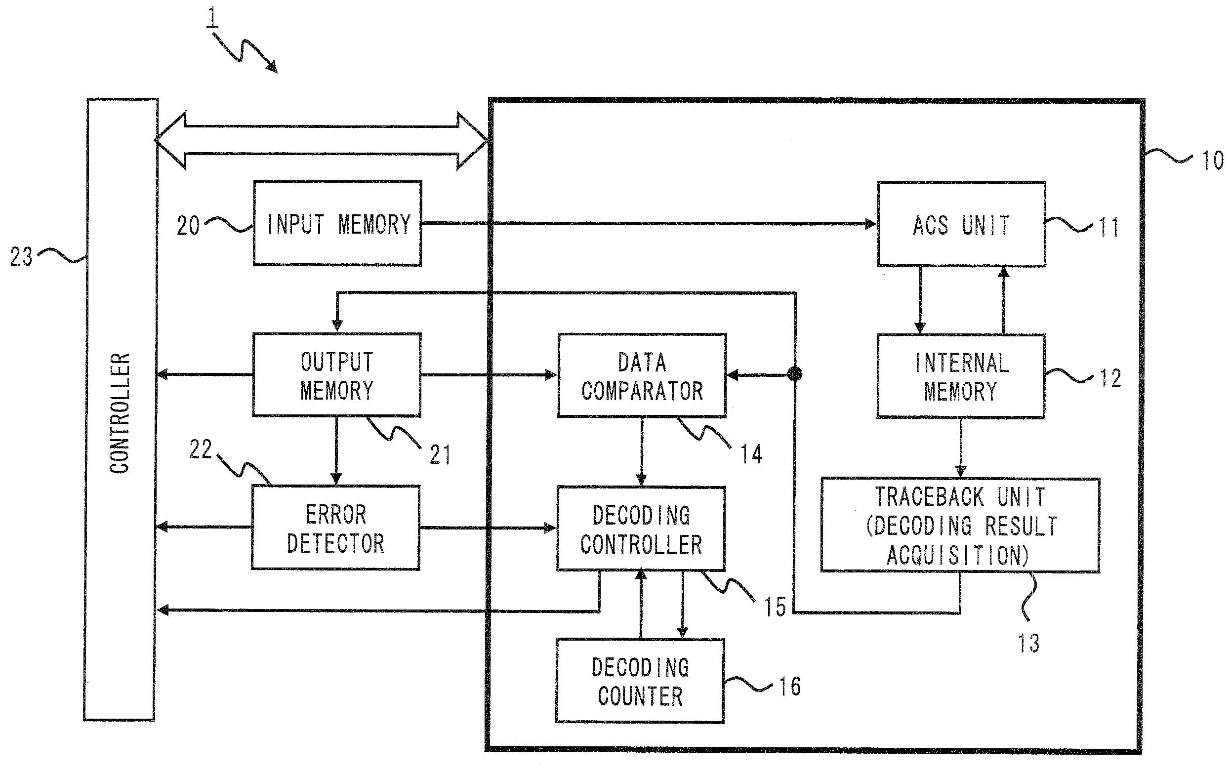
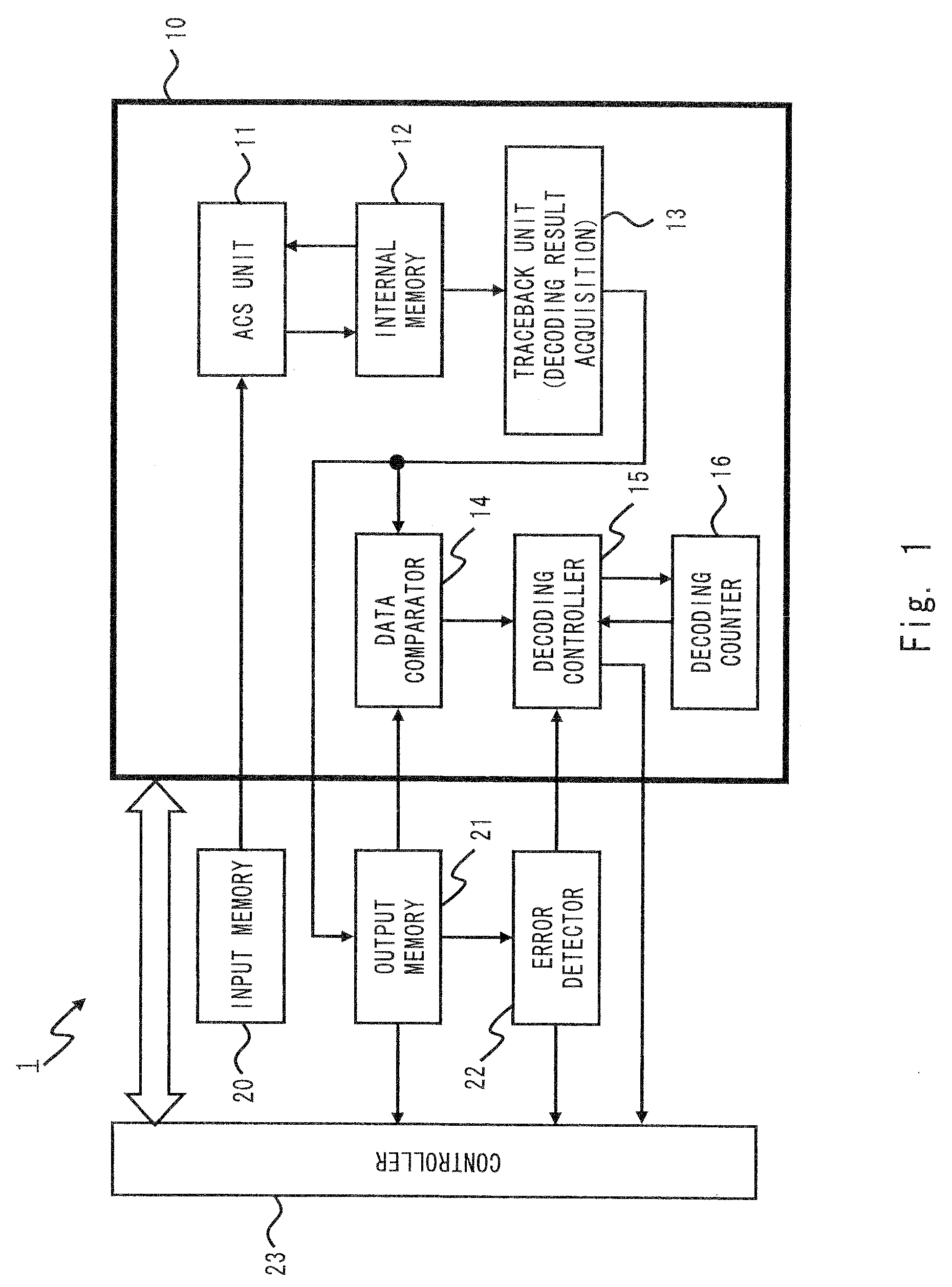
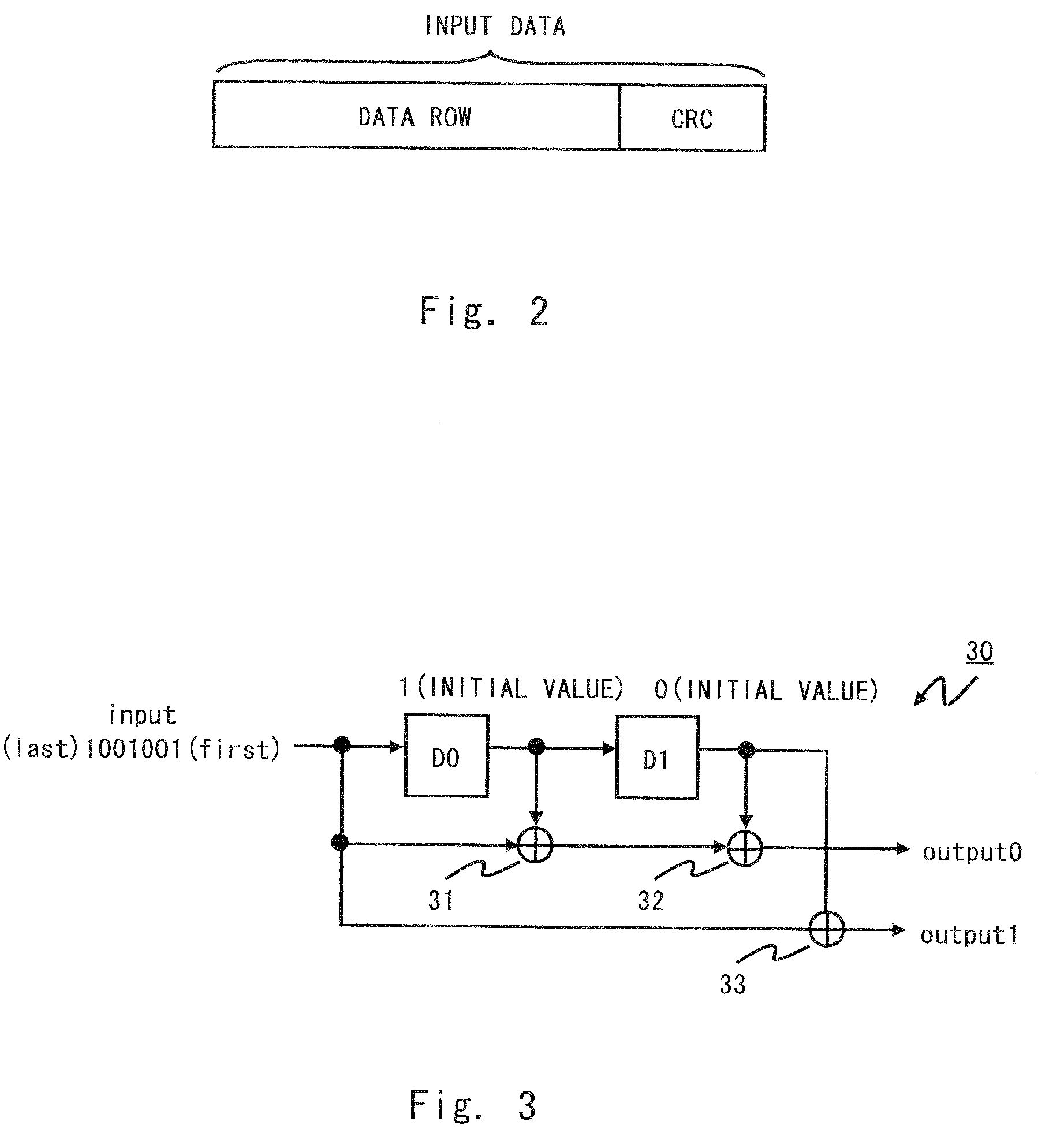
[0032]An exemplary embodiment of the present invention is described hereinafter with reference to the drawings. FIG. 1 is a block diagram showing a Viterbi decoding apparatus 1 according to the exemplary embodiment. Referring to FIG. 1, the Viterbi decoding apparatus 1 includes a decoder 10, an input memory 20, an output memory 21, an error detector 22, and a controller 23. In the followings, a case where the Viterbi decoding apparatus 1 receives data that has been encoded based on the convolutional coding algorithm by an encoder at the transmitting end and decodes the input data based on the Viterbi decoding algorithm is described. Further, the input data received by the Viterbi decoding apparatus 1 contains an encoded error detecting code (e.g. a cyclic redundancy check (CRC) code) added to a data row to be transmitted. FIG. 2 is a conceptual diagram showing the data before encoding that is used in the exemplary embodiment.

[0033]The decoder 10 includes an ACS unit 11, an internal ...


PUM


Abstract

The decoding apparatus includes an ACS unit to execute an add-compare-select operation on encoded received data, and an error detector to detect whether there is an error in decoded data calculated based on the executed add-compare-select operation, and if there is an error in the decoded data, the ACS unit additionally executes the add-compare-select operation on the received data.

Description

BACKGROUND[0001]1. Field of the Invention[0002]The present invention relates to a decoding apparatus and a decoding method and, particularly, to a decoding apparatus and a decoding method that perform decoding of tail-biting convolutional coded data using the Viterbi algorithm.[0003]2. Description of Related Art[0004]In a radio communication system such as a mobile communication system, communication is performed using data that is encoded in order to improve the error correction capability of data communicated by a radio signal. Convolutional coding is often used as an encoding technique. There are two types of convolutional coding: terminating convolutional coding and tail-biting convolutional coding.[0005]The terminating convolutional coding generates encoded data by setting a termination bit having a predetermined value to the initial state of an encoder and at the end of a data row to be transmitted. Further, because the value of the initial state of the encoder is known in a d...

Claims


Application Information

Patent Timeline
IPC IPC(8): H03M13/41H03M13/23
CPCH03M13/09H03M13/4161H03M13/413H03M13/3753H03M13/00H03M13/01H03M13/41
Inventor TAKANASHI, MITSUNORI
Owner RENESAS ELECTRONICS CORP
Why Eureka
Try Eureka