Water cooling apparatus in power transmission system of boat propulsion unit

a technology of water cooling apparatus and power transmission system, which is applied in the direction of marine propulsion, vessel construction, propulsive elements, etc., can solve the problems of large amount of water required, affecting the lifetime of the transmission unit, and increasing so as to reduce the magnitude of the support moment and relieve the strain on the rear portion of the hull. , the effect of reducing the total cross-sectional area of the cooling water passage behind the axi

Active Publication Date: 2009-07-09
YAMAHA MOTOR CO LTD
View PDF4 Cites 29 Cited by
  • Summary
  • Abstract
  • Description
  • Claims
  • Application Information

AI Technical Summary

Benefits of technology

[0012]The transmission unit preferably includes a pair of left and right front bolts extending vertically to fasten the front portion of the transmission case to the case and a pair of left and right rear bolts extending vertically to fasten the rear portion of the transmission case to the case, and the width dimension between the left and the right front bolts is preferably larger than the width dimension between the left and the right rear bolts in the width direction of the hull.
[0021]Accordingly, the center of gravity of the boat propulsion unit can be set closer to the rear portion of the hull while avoiding contact of the rear portion of the hull with the front outer surface of the case. As a result, it is possible to reduce the magnitude of the support moment generated when the rear portion of the hull supports the boat propulsion unit. As a result, it is possible to relieve strain on the rear portion of the hull.
[0022]A total cross-sectional area of the cooling water passage in front of the axis of the transmission case is preferably smaller than a total cross-sectional area of the cooling water passage behind the axis.
[0023]Therefore, if the total cross-sectional area of the cooling water passage behind the axis is increased while minimizing the total cross-sectional area of the cooling water passage...

Problems solved by technology

Such heating of the transmission unit affects the lifetime of the transmission unit.
In this case, a large amount of water is required to flow through the cooling water passage to sufficiently cool the...

Method used


Image

  • Water cooling apparatus in power transmission system of boat propulsion unit
  • Water cooling apparatus in power transmission system of boat propulsion unit
  • Water cooling apparatus in power transmission system of boat propulsion unit

Examples


first preferred embodiment

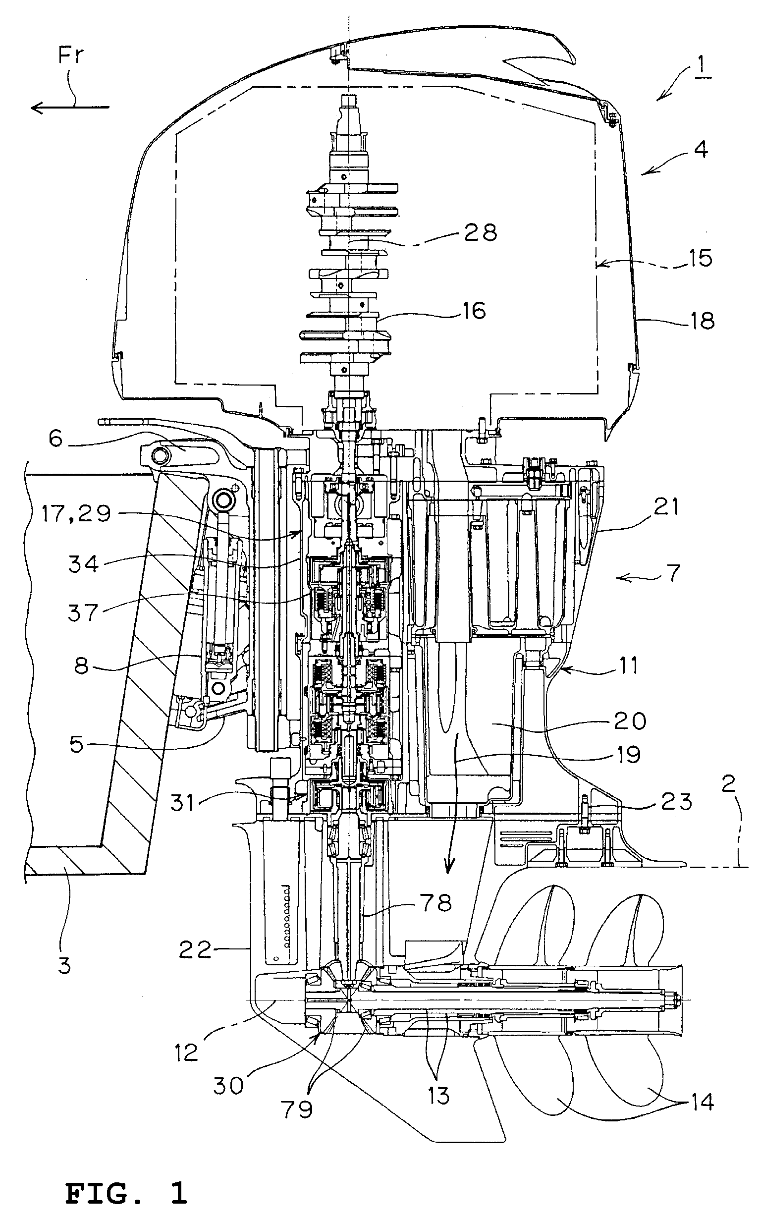
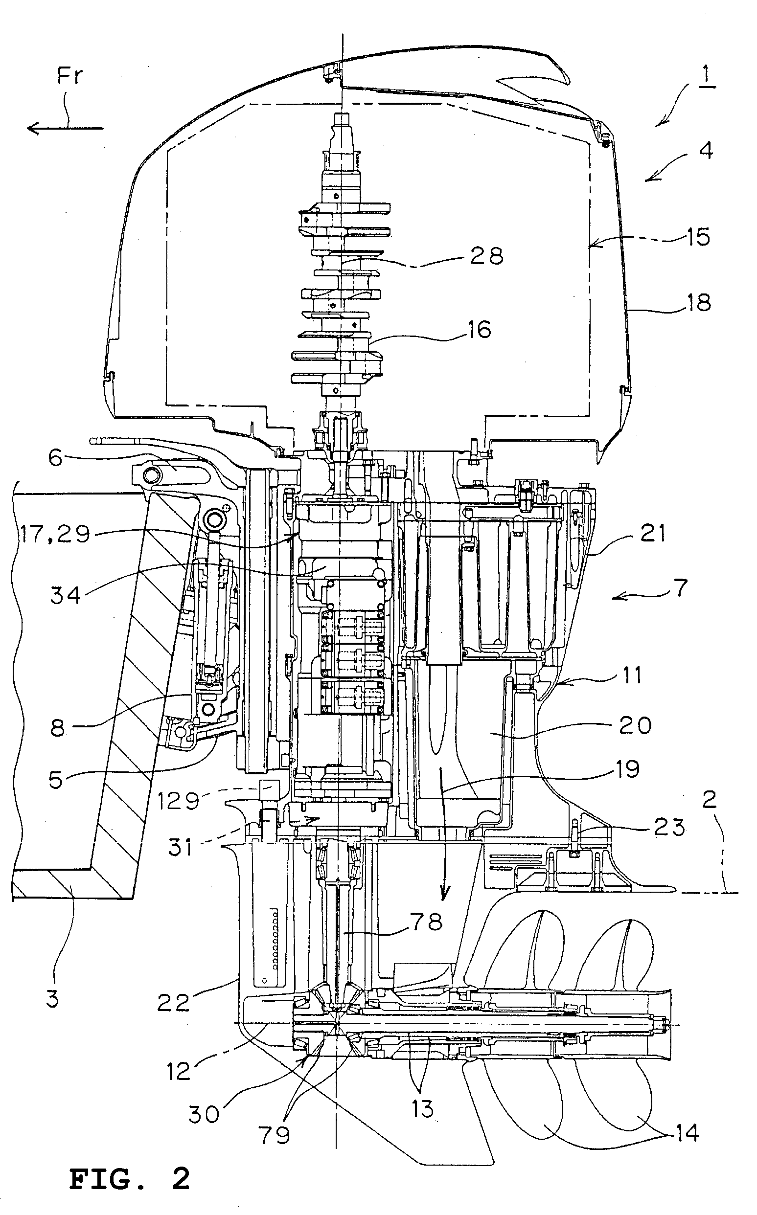
[0059]In order to describe the present invention in more detail, a first preferred embodiment will be described hereinafter with reference to FIGS. 1 to 13.

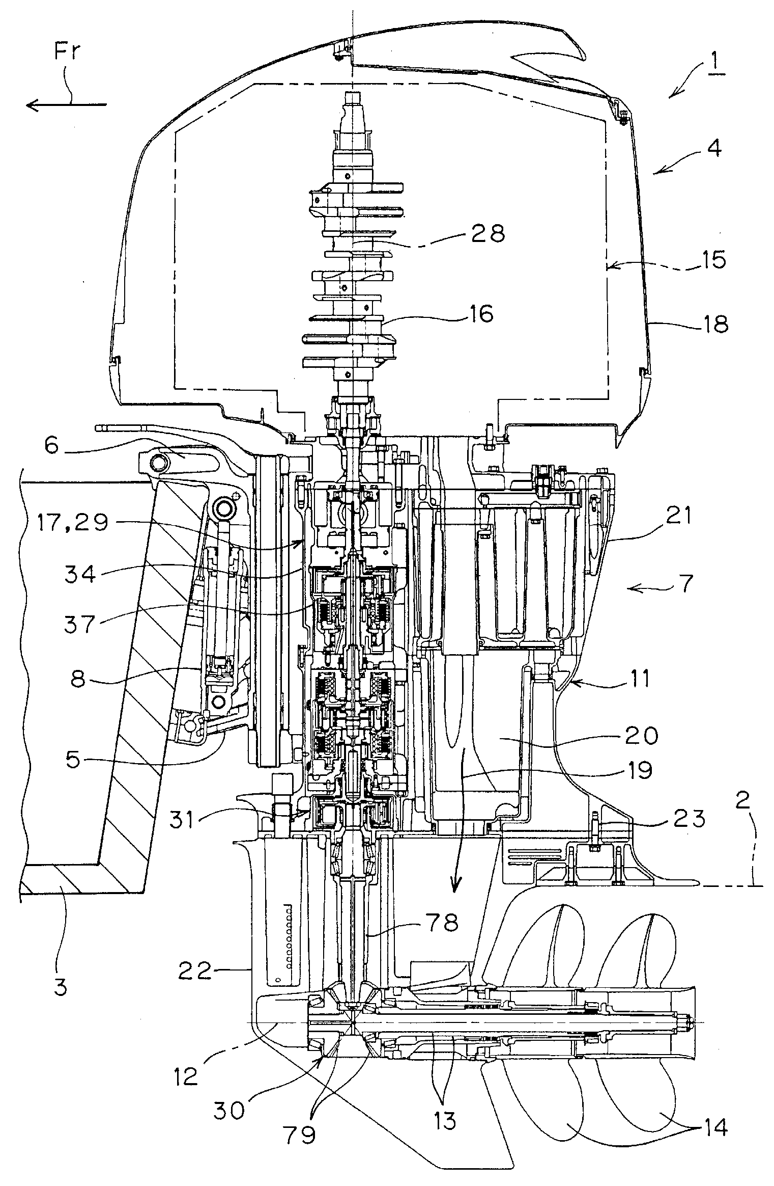
[0060]In FIGS. 1 and 2, reference numeral 1 denotes a boat, and the arrow Fr indicates a forward direction in which the boat 1 is propelled. The term “right and left” described below designates a width direction of the boat 1 with respect to the forward direction.

[0061]The boat 1 includes a hull 3 capable of floating on water 2 and a boat propulsion unit 4 that is detachably supported at the rear of the hull 3 so as to propel the boat 1. The surface of the water 2 shown by a double-dashed line in FIGS. 1 and 2 indicates a water surface when the boat 1 is traveling forward. The surface of the water 2 rises slightly when the boat 1 stops.

[0062]The boat propulsion unit 4 includes a clamp bracket 5 detachably supported at the rear of the hull 3, a swivel bracket 6 pivoted by the clamp bracket 5 for fore-and-aft swinging rearward and ...

second preferred embodiment

[0129]For the purpose of describing the present invention in further detail, the second preferred embodiment of the invention is described with reference to FIG. 14 attached hereto.

[0130]In FIG. 14, the lower end portion of the cooling water passage 130 preferably has a substantially annular shape in the plan sectional view of the transmission unit 29 at the case bottom 43. With this unique structure, the cooling water 126 flows more smoothly in the lower end portion of the cooling water passage 130. Therefore, the oil 97 in the oil pan 110 can be further effectively cooled with the cooling water 126.

third preferred embodiment

[0131]Description will be hereinafter made of the third preferred embodiment of the present invention in detail with reference to FIG. 15 attached hereto.

[0132]In FIG. 15, the lower end portion of the cooling water passage 130 preferably has a substantially C-shape configuration that is substantially annular in the plan sectional view of the transmission unit 29 at the case bottom 43. A plurality, for example two, drain holes 131, each formed at each end of the substantially c-shaped cooling water passage, are formed on the circumference around the axis 28.

[0133]With this unique structure, the cooling water respectively flows toward each of the drain holes 131 from the upstream side of the cooling water passage 130 in the lower end portion of the cooling water passage 130. The cooling water 126 can thereby be prevented from flowing unevenly or stagnating in the lower end portion of the cooling water passage 130. Accordingly, the cooling water 126 can flow throughout each portion of ...


PUM


Abstract

A water cooling apparatus in a power transmission system of a boat propulsion system includes a transmission unit that changes the speed of an output from an engine and then transmits the output to a propeller shaft. The transmission unit includes a cylindrical transmission case with an axis extending vertically, a transmission device housed in the transmission case and arranged to change the speed of an input, and a cooling water passage formed in the transmission case for flowing cooling water. In the plan sectional view of the transmission unit, the cooling water passage is formed in at least one of a side portion or a rear portion of the transmission case. As a result, strain on a rear portion of a hull that supports a boat propulsion unit is prevented and minimized, while a transmission unit is sufficiently cooled with cooling water.

Description

BACKGROUND OF THE INVENTION[0001]1. Field of the Invention[0002]The present invention relates to a power transmission system of a boat propulsion unit including a transmission unit that receives an output from an engine, changes its speed, and transmits the output to a propeller. More specifically, the present invention relates to a water cooling apparatus for cooling the transmission unit with cooling water.[0003]2. Description of the Related Art[0004]The above type of conventional boat propulsion unit is disclosed in WO 2007 / 007707, which discloses a boat propulsion unit including a case which is disposed right behind a hull and is supported at the rear of the hull, a propeller supported in a lower portion of the case, and a transmission unit housed in the case to receive an engine output, change its speed, and transmit the engine output to the propeller.[0005]In an attempt to propel a boat, if an engine output is input to the transmission unit of the power transmission system, th...

Claims


Application Information

Patent Timeline
IPC IPC(8): F16H57/04B63H20/14B63H20/32
CPCB63H20/285Y10T74/2189F01P3/202
Inventor OKABE, YOSHIHIKOYAMAUCHI, HIROTOSHI
Owner YAMAHA MOTOR CO LTD
Why Eureka
Try Eureka