Flash memory device with isolation structure

a technology of isolation structure and flash memory, which is applied in the direction of semiconductor devices, electrical devices, transistors, etc., can solve the problems of interference phenomenon, interference phenomenon, narrow inter-gate distance, etc., and achieve the effect of reducing cell leakage, reducing threshold voltage (vt), and reducing disturbance effects

Inactive Publication Date: 2009-07-09
SK HYNIX INC
View PDF3 Cites 1 Cited by
  • Summary
  • Abstract
  • Description
  • Claims
  • Application Information

AI Technical Summary

Benefits of technology

[0010]An embodiment of the present invention provides a flash memory device and a method of manufacturing in which buried floating gates are formed at portions of trenches for forming isolation structures and are isolated by the isolation structures, thereby avoiding the interference between the floating gates, and as the sidewalls of the trenches become channels of the flash memory device, the channel length becomes longer compared with the related art and reduce the cell leakage, the threshold voltage (Vt) can be minimized, and disturb effects can be reduced.

Problems solved by technology

As the dielectric film including the floating gate and the control gates are formed within the narrow active space, the inter-gate distance becomes narrow and the interference phenomenon becomes more problematic.
Accordingly, the distance between adjacent first polysilicon films is also reduced, resulting in an interference phenomenon.
Furthermore, the threshold voltage (Vt) of the semiconductor substrate is changed due to the interference phenomenon between the floating gates.
As the interference phenomenon increases in the direction of the control gates, device characteristics are inevitably degraded.
The interference phenomenon lowers the program speed of the flash cell and results in degraded quality.

Method used


Image

  • Flash memory device with isolation structure
  • Flash memory device with isolation structure
  • Flash memory device with isolation structure

Examples


first embodiment

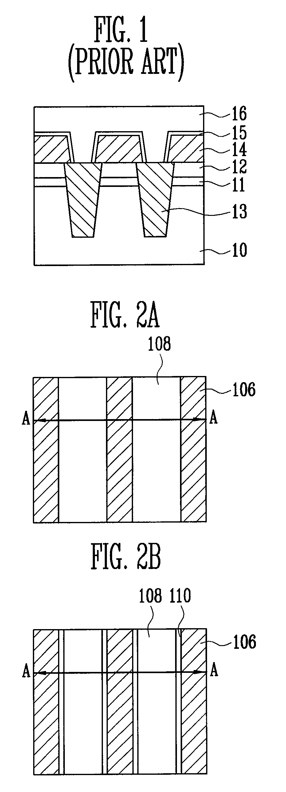
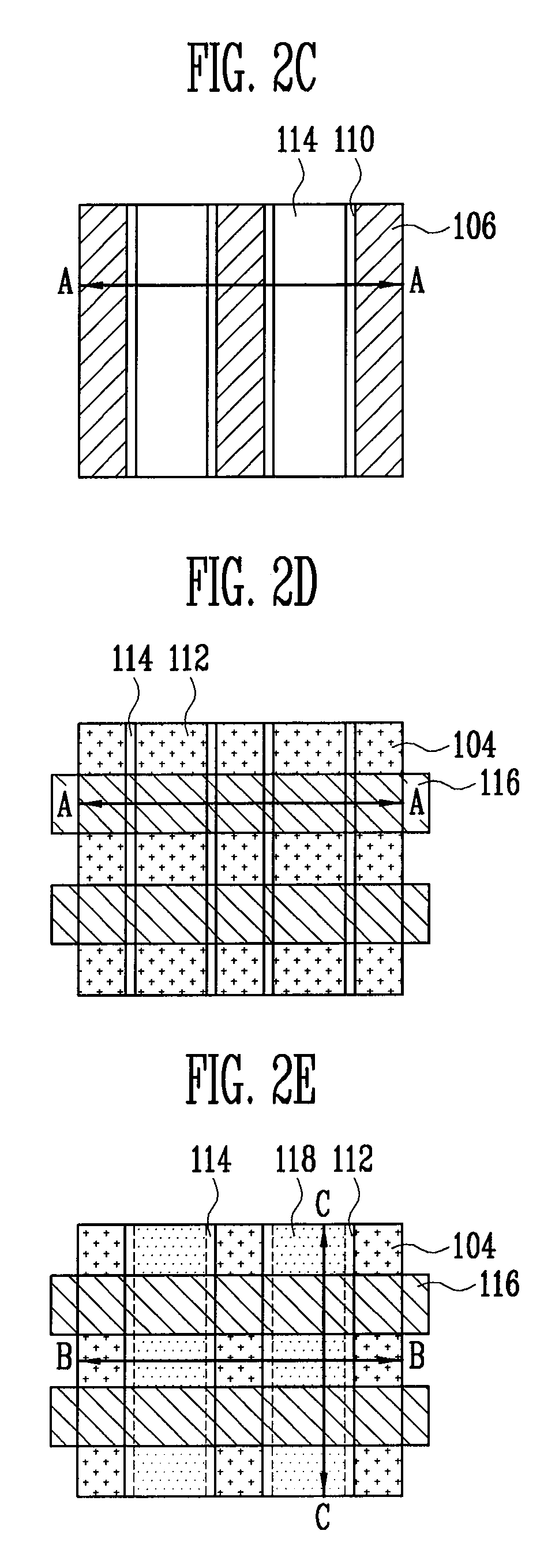
[0020]FIGS. 2A to 2E are layout diagrams illustrating a flash memory device to which a self-aligned STI is applied according to the present invention. FIGS. 3A to 3F are cross-sectional views of the flash memory devices corresponding to the layout diagrams of FIGS. 2A to 2E, respectively.

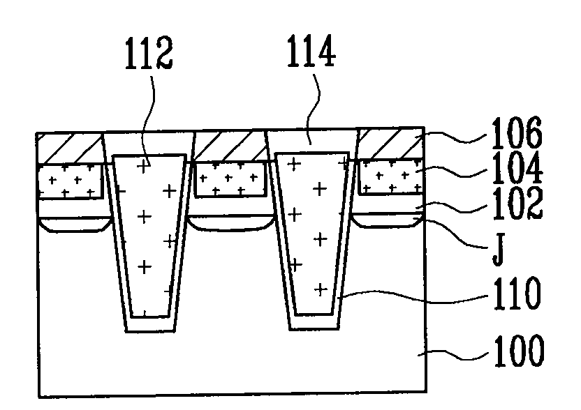
[0021]FIG. 3A is a cross-sectional view of the flash memory device taken along line A-A in FIG. 2A. Referring to FIGS. 2A and 3A, a high concentration ion implantation process is performed to form a junction unit J on a semiconductor substrate 100. A first oxide film 102 is thickly formed on the semiconductor substrate 100. Since a high concentration of ions has been injected into the semiconductor substrate 100, the first oxide film 102 can be thickly formed using a low thermal process. The first oxide film 102 may be formed to a thickness of about 300 Å to about 500 Å.

[0022]A first polysilicon film 104 and a hard mask film 106 are sequentially formed on the first oxide film 102. The hard mask film...

second embodiment

[0039]FIGS. 4A to 4D are layout diagrams illustrating a flash memory device to which a general STI is applied according to the present invention. FIGS. 5A to 5E are cross-sectional views of the flash memory devices corresponding to the layout diagrams of FIGS. 4A to 4D, respectively.

[0040]FIG. 5A is a cross-sectional view of the flash memory device taken along line D-D in FIG. 4A.

[0041]Referring to FIGS. 4A and 5A, a high concentration ion implantation process is performed to form junction units J on a semiconductor substrate 200. A first oxide film 202 is thickly formed on the semiconductor substrate 200. Since the ion of a high concentration has been injected into the semiconductor substrate 200, the first oxide film 202 can be formed thickly even using a low thermal process. The first oxide film 202 may be formed to a thickness of about 300 Å to about 500 Å.

[0042]The first oxide film 202 and the semiconductor substrate 200 are selectively etched by photolithography and etch proce...


PUM


Abstract

A flash memory device includes trenches that are formed at regions on a semiconductor substrate spaced apart from one another at predetermined distances, buried floating gates buried into the trenches, a plurality of isolation structures formed between the buried floating gates, and a dielectric film and a control gate formed on the buried floating gates

Description

CROSS REFERENCES TO RELATED APPLICATIONS[0001]The present application is a division of U.S. patent application Ser. No. 11 / 479,525, filed on Jun. 30, 2006, which claims priority to Korean patent application number 10-2005-107426, filed on Nov. 10, 2005, which is incorporated by reference in its entirety.BACKGROUND[0002]The present invention relates to a method of manufacturing a flash memory device, and more particularly, to a flash memory device which can minimize the interference phenomenon between adjacent floating gates and a method of manufacturing the same.[0003]Recently, in the manufacturing of flash memory devices, the spaces in which a unit active region and a unit field region will be formed are continuously being reduced as the level of integration is increased. As the dielectric film including the floating gate and the control gates are formed within the narrow active space, the inter-gate distance becomes narrow and the interference phenomenon becomes more problematic.[...

Claims


Application Information

Patent Timeline
Patent Type & Authority Applications(United States)
IPC IPC(8): H01L29/788
CPCH01L27/115H01L27/11521H01L27/11519H10B41/10H10B69/00H10B41/30H10B99/00
Inventor KIM, KI SEOG
Owner SK HYNIX INC
Why Eureka
Try Eureka