

Motor drive apparatus equipped with dynamic braking circuit fault detection capability
a technology of dynamic braking circuit and motor drive, which is applied in the direction of motor/generator/converter stoppers, dynamo-electric converter control, stopping arrangements, etc., can solve the problems of increasing apparatus cost and apparatus cost, and achieve the effect of low cost and short check tim
- Summary
- Abstract
- Description
- Claims
- Application Information
AI Technical Summary
Benefits of technology
Problems solved by technology
Method used
Image

Examples
first embodiment
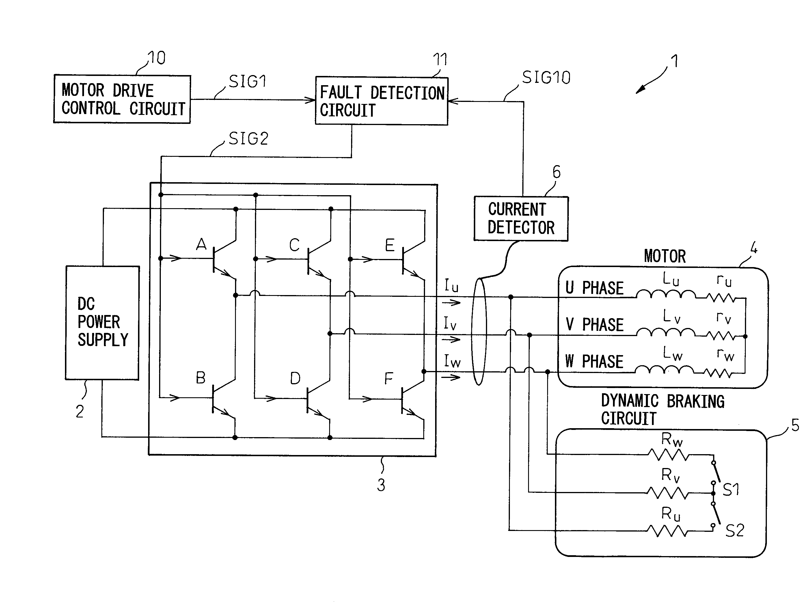
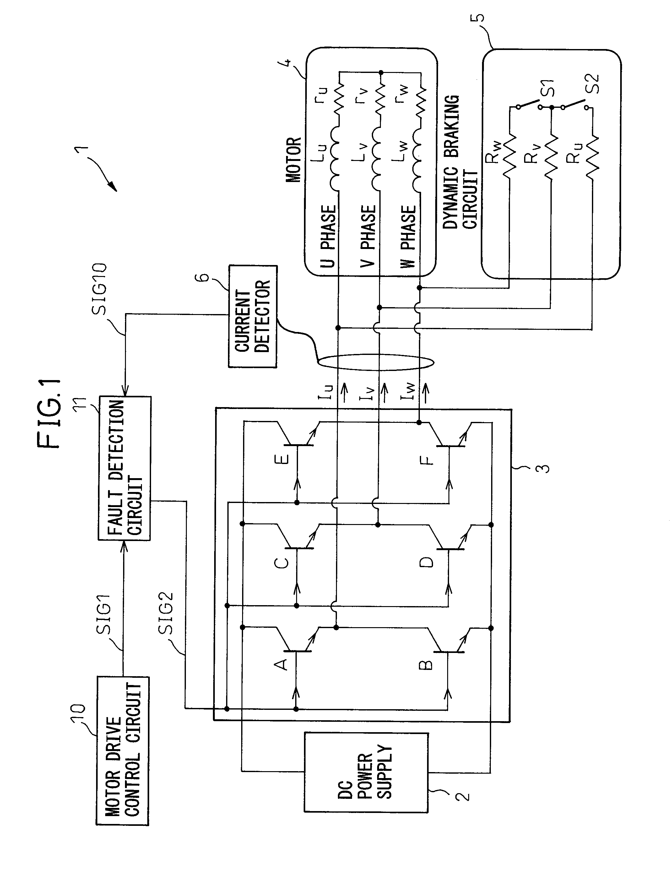
[0028]FIG. 1 is a block diagram schematically showing the configuration of a motor drive apparatus according to the present invention.
[0029]In the motor drive apparatus 1 generally shown in FIG. 1, a DC power supply 2 converts AC power, supplied from an AC power supply not shown, into DC power. The DC power from the DC power supply 2 is supplied to a synchronous motor (hereinafter referred to as the motor) 4 via a power transistor unit 3 comprising power transistors A to F. When the power to the motor 4 is cut off while the motor 4 is running, a dynamic braking circuit 5 actuates switches S1 and S2, i.e., relay contacts, so that the power is dissipated through resistors Ru, Rv, and Rw in the dynamic braking circuit 5.
[0030]A motor drive control circuit 10 outputs a dynamic braking circuit control signal SIG1, in response to which a fault detection circuit 11 generates a power transistor control signal SIG2 for controlling the driving / stopping of the motor 4 and supplies it to the po...
second embodiment
[0059]FIG. 5 is a block diagram schematically showing the configuration of a motor drive apparatus according to the present invention.
[0060]In the motor drive apparatus 15 generally shown in FIG. 5, the DC power output from a DC power supply 52 is supplied to a motor 54 via a power transistor unit 53 comprising power transistors A to F. When the power to the synchronous motor (hereinafter referred to as the motor) 54 is cut off while the motor 54 is running, a dynamic braking circuit 55 actuates switches S1 and S2, i.e., relay contacts, so that the power is dissipated through resistors Ru, Rv, and Rw in the dynamic braking circuit 55.
[0061]A motor drive control circuit 60 outputs a dynamic braking circuit control signal SIG1, in response to which a fault detection circuit 61 generates a power transistor control signal SIG2 for controlling the driving / stopping of the motor 4 and supplies it to the power transistors A to F in the power transistor unit 53. A current detector 56 detects...
PUM
 Abstract
Description
Claims
Application Information