Mobile communication terminal

a terminal and mobile technology, applied in the direction of portable computers, instruments, protective materials, etc., can solve the problems of high fabrication cost, large amount of time and inconvenience in assembling the terminal, and so as to achieve the effect of improving the degree of freedom in the shape of the terminal and facilitating and inexpensively integrating

Active Publication Date: 2009-07-09
TOSHIBA CLIENT SOLUTIONS CO LTD
View PDF8 Cites 8 Cited by
  • Summary
  • Abstract
  • Description
  • Claims
  • Application Information

AI Technical Summary

Benefits of technology

[0008]The present invention has been made in view of the above-described circumstance. It is an object of the present invention to provide a mobile communication terminal that easily and inexpensively achieves integration between a casing and an antenna and enables further downsizing and improvement of a degree of freedom in shape of a terminal casing.
[0010]Therefore, the antenna element is formed by printing an conductive material pattern on a casing face, and thus, can be configured easily and inexpensively. Moreover, the antenna element can be formed on a curved face of the casing, thus making it possible to improve the degree of freedom in shape of the casing.
[0011]Namely, in the case where an antenna device is additionally fabricated, and is mounted on the casing, there is a need for fabricating a dedicated mold, thus resulting in higher fabrication cost. There is also a need for the step of mounting the antenna device on the casing, thus requiring a large amount of time and inconvenience in assembling a terminal. Further, in order to house the antenna device in the casing, a limitation naturally occurs in shape of the casing, and the degree of freedom in shape of the casing is lowered.
[0013]Therefore, an antenna element is formed by printing a conductive material pattern on an antenna substrate, and thus, can be configured easily and inexpensively without additionally fabricating a mold or the like. Moreover, for example, the antenna substrate is molded in advance in accordance with the shape of the casing or is made of a member having flexibility, thereby making it possible to install the antenna unit on a curved face of the casing or the like. Consequently, the degree of freedom in shape of the casing can be improved.
[0014]Further, the antenna element is formed on the antenna substrate without being directly formed on a face of the casing. As a consequence, a material having heat resistance or acid resistance is used as an antenna substrate, thereby making it possible to carry out arbitrary surface processing such as plating processing with respect to the antenna element. In addition, there is no need for using a material having heat resistance or acid resistance as a material for the casing, thus making it possible to achieve cost reduction as well as to improve the degree of freedom in choosing a material for the casing.

Problems solved by technology

Namely, in the case where an antenna device is additionally fabricated, and is mounted on the casing, there is a need for fabricating a dedicated mold, thus resulting in higher fabrication cost.
There is also a need for the step of mounting the antenna device on the casing, thus requiring a large amount of time and inconvenience in assembling a terminal.
Further, in order to house the antenna device in the casing, a limitation naturally occurs in shape of the casing, and the degree of freedom in shape of the casing is lowered.

Method used


Image

  • Mobile communication terminal
  • Mobile communication terminal
  • Mobile communication terminal

Examples


first embodiment

Example 1

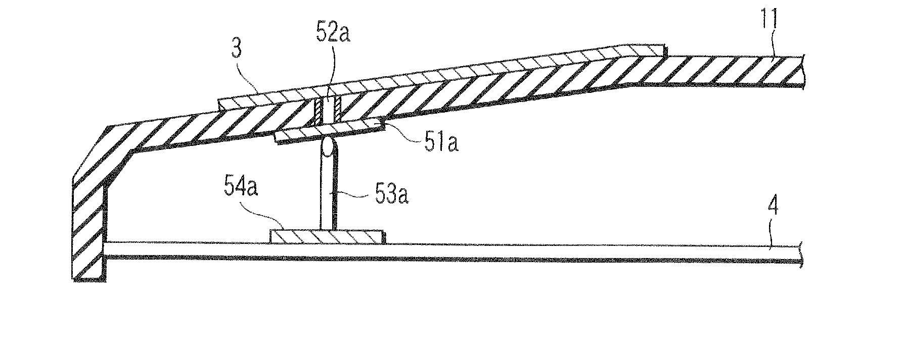
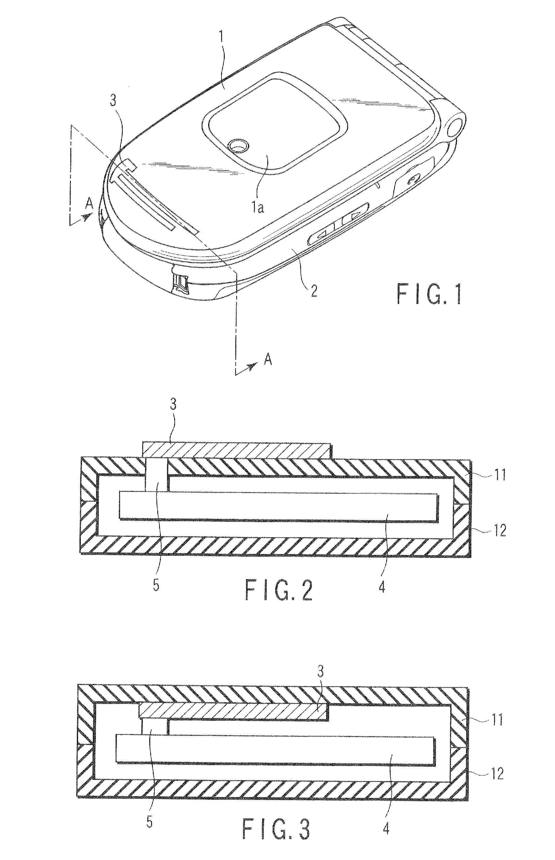
[0054]FIG. 1 is a perspective view showing a configuration of Example 1 of a cellular phone according to a first embodiment of the present invention. FIG. 2 is a sectional view taken along the line A-A of the cellular phone shown in FIG. 1 and is a view showing Example 1 of an allocation structure of an antenna element.

[0055]The cellular phone connects an upper casing 1 made of an electrically nonconductive material with a lower casing 2 via a hinge mechanism. The upper casing 1 is composed of an outer cover 11 having a sub-display allocated thereon, and an inner cover 12 having a main display (not shown) allocated thereon.

[0056]At a distal end of a surface of the outer cover 11, an antenna element 3 made of an electrically conductive material pattern having a thickness of about 10 μm is formed by means of printing and plating. Pad printing, screen printing, offset printing or the like is used as a printing method. For example, gold, silver, or copper is used for electrical...

second embodiment

Example 1

[0081]FIG. 14 is a perspective view showing a configuration of a cellular phone which is a second embodiment of a mobile communication terminal according to the present invention. FIG. 15 is a sectional view taken along the line B-B of an upper casing in FIG. 14 and is a view showing Example 1 of an allocation structure of an antenna element. In the figures, like constituent elements shown in FIGS. 1 and 2 are designated by like reference numerals, and a detailed description will not be described here.

[0082]The cellular phone according to the present embodiment fabricates an antenna unit 8 by printing and plating an antenna element 82a on a non-metal antenna substrate 81a so as to fix the antenna unit 8 onto the upper casing 1 of the cellular phone.

[0083]The antenna substrate 81a is made of. for example, an acrylonitrile butadiene styrene (ABS) resin or a polyethylene terephthalate (PET) thin film, and has flexibility in order to take along a curved shape of a surface of th...

example 2

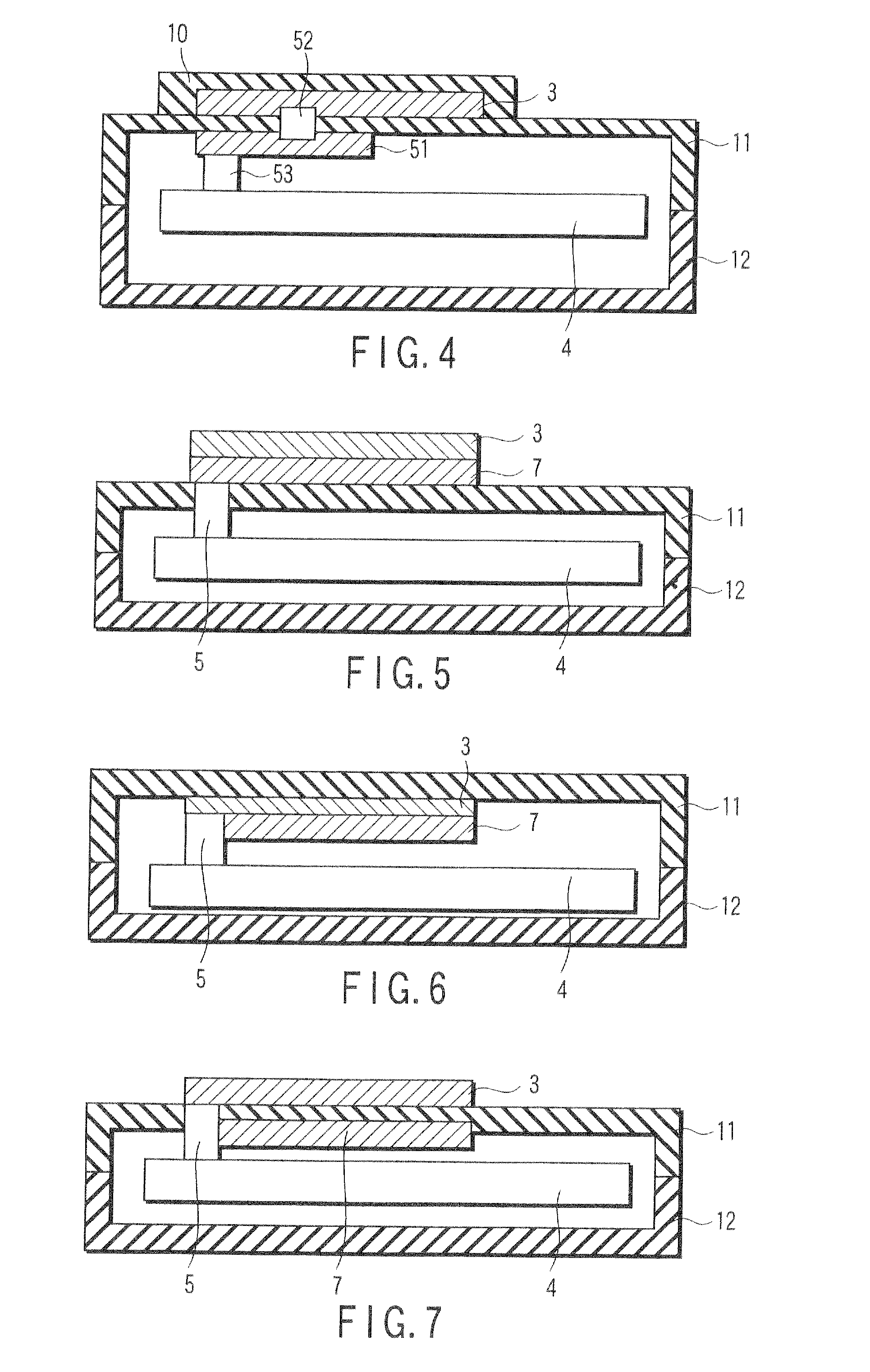
[0087]In Example 2 of the cellular phone according to the second embodiment of the invention, as shown in FIG. 16, an antenna unit 8 is housed in a casing 1 so as to fix an antenna substrate 81b of the antenna unit on a back face of an outer cover 11 in the upper casing 1. The antenna element 82a and a radio power supply circuit of a printed circuit board 4 are connected to each other by a connecting element 5. With such a configuration, irregularities on a surface of the outer cover 11 using an antenna unit 8 are eliminated, so that the surface of the outer cover 11 can be flatly formed, thereby making it possible to improve a design property. Although there is a need for allocating a space for housing the antenna unit 8 in the casing 1, the antenna unit 8 is made of a thin plate body, and consequently, there is no concern of an increase in the thickness of the casing 1.


PUM


Abstract

An antenna element made of an electrically conductive material pattern is printed and formed on a face of a casing made of an electrically nonconductive material having a circuit board housed therein, and the antenna element and the circuit board are electrically connected to each other by a connecting element.

Description

CROSS-REFERENCE TO RELATED APPLICATIONS[0001]The present application is a Continuation Application of U.S. application serial No. 11 / 496,822 filed Aug. 1, 2006, which is based upon and claims the benefit of priority from prior Japanese Patent Application No. 2006-111296, filed Apr. 13, 2006, the entire contents of which are incorporated herein by reference.BACKGROUND OF THE INVENTION[0002]1. Field of the Invention[0003]The present invention relates to a mobile communication terminal such as a cellular phone, a personal digital assistant (PDA) or a personal computer (PC) and more particularly, to a mobile communication terminal that includes a built-in antenna.[0004]2. Description of the Related Art[0005]Recently, in a mobile communication terminal, represented by a cellular phone, a PDA, or a PC, there has been added a variety of diversified functions such as a web access function or a remote control function relevant to a peripheral device, a function serving as a season ticket, an...

Claims


Application Information

Patent Timeline
Patent Type & Authority Applications(United States)
IPC IPC(8): H01Q1/24
CPCG06F1/1616H01R12/718G06F1/1656G06F1/1698H01F1/26H01Q1/40H01Q9/0407H01Q9/0421H01Q9/16H01Q9/30H01R2201/02H04M1/026H05K1/0284H05K3/182G06F1/165H01R2201/16H01Q1/243H01Q1/38
Inventor TSUJIMURA, AKIHIROHOTTA, HIROYUKIAMANO, TAKASHISATO, KOICHI
Owner TOSHIBA CLIENT SOLUTIONS CO LTD
Why Eureka
Try Eureka