Synchronous Rectifier

a synchronous rectifier and rectifier technology, applied in the direction of electric variable regulation, process and machine control, instruments, etc., can solve the problems of weak noise relative to the above rectifier, difficult to improve the efficiency of the above rectifier beyond a degree compared to the general llc resonant converter, etc., to achieve low cost, high efficiency, and stability

Active Publication Date: 2009-07-09
SEMICON COMPONENTS IND LLC
View PDF7 Cites 43 Cited by
  • Summary
  • Abstract
  • Description
  • Claims
  • Application Information

AI Technical Summary

Benefits of technology

[0016]In some embodiments, the on / off states of the switches SR1 and SR2 can be precisely controlled by sensing the voltage induced to the secondary coil of the transformer without adding components such as a photocoupler or a transformer, and hence, a synchronous rectifier with a low cost, stability, and high efficiency can be realized.

Problems solved by technology

However, the voltage to determine the turn-off time of the secondary coil switch, sensed by the synchronous rectifier driven by the above-noted method is a low voltage (e.g., several tens of mV), it is weak relative to the noise.
Further, it is difficult to control the off time of the secondary coil switch because of the influence by a parasitic component on a printed circuit board (PCB) layout.
For both of these reasons, it is difficult to improve the efficiency of the above rectifier beyond a degree compared to the general LLC resonant converter.
However, in order to implement the method, an additional component such as a photocoupler or a transformer is required so as to transmit a control signal of the primary coil of the transformer to the secondary coil, and hence the production cost of the synchronous rectifier in increased.
Also, when the switch associated with the primary coil of the transformer is turned on / off with a frequency that is less than the resonance frequency of the transformer, resonance of the current flowing to the secondary coil of the transformer can be terminated before the switch of the primary coil of the transformer is turned off, and hence, the switch of the secondary coil of the transformer may not be turned off at an appropriate time.
Accordingly, the current may flow in the reverse direction to reduce efficiency.

Method used


Image

  • Synchronous Rectifier
  • Synchronous Rectifier
  • Synchronous Rectifier

Examples


Embodiment Construction

[0024]In the following detailed description, only certain exemplary embodiments of the present invention have been shown and described, simply by way of illustration. As those skilled in the art would realize, the described embodiments may be modified in various different ways, all without departing from the spirit or scope of the present invention. Accordingly, the drawings and description are to be regarded as illustrative in nature and not restrictive. Like reference numerals designate like elements throughout the specification.

[0025]Throughout this specification and the claims that follow, when it is described that an element is “coupled” to another element, the element may be “directly coupled” to the other element or “electrically coupled” to the other element through a third element.

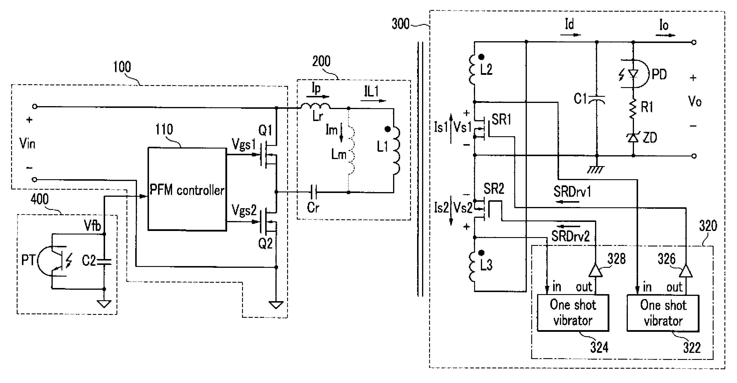
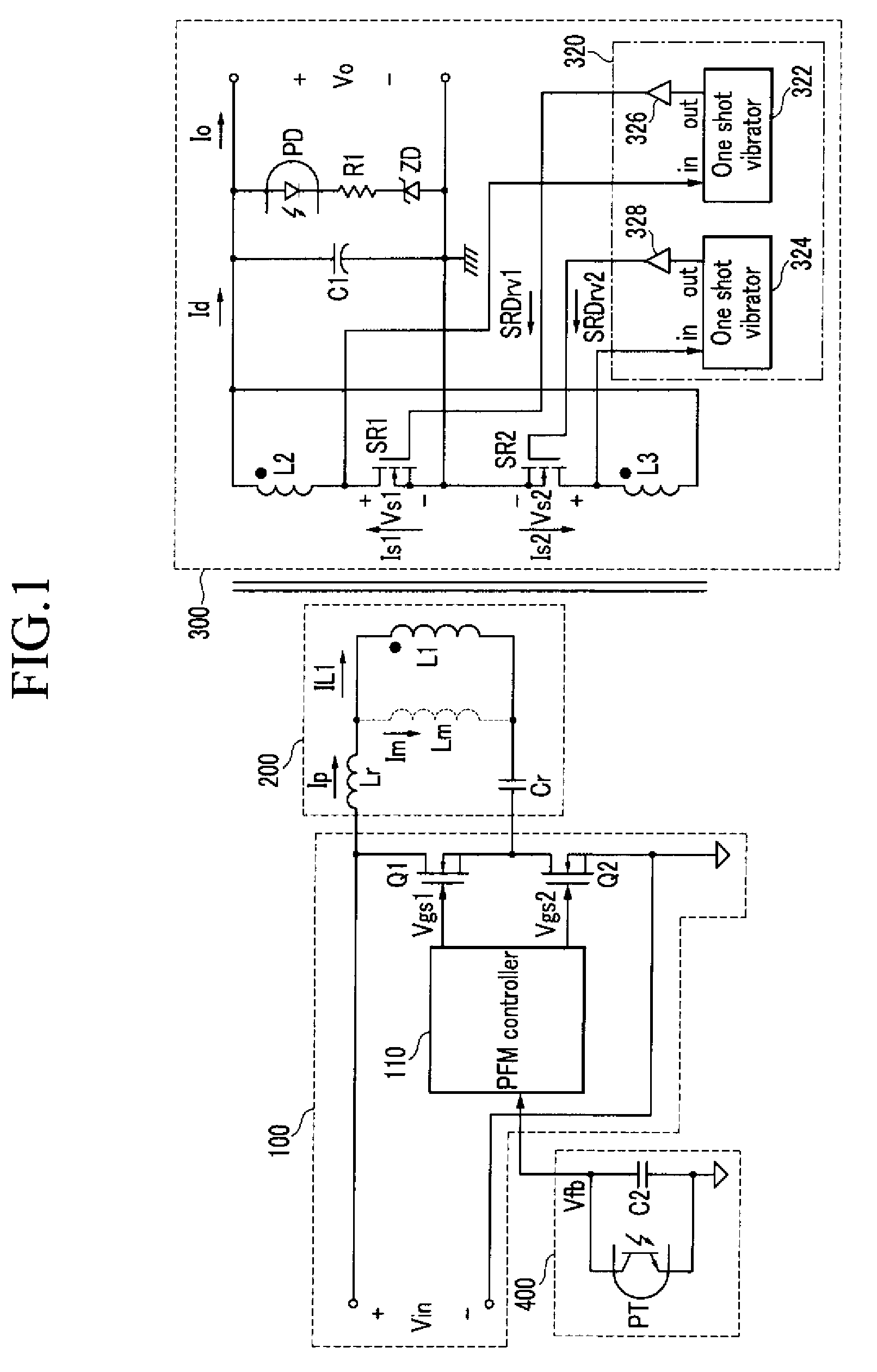
[0026]FIG. 1 shows an embodiment of a synchronous rectifier. The synchronous rectifier can include a square wave generator 100, a resonator 200, an output unit 300, and a feedback circuit 400.

[002...


PUM


Abstract

This invention relates to a synchronous rectifier for LLC resonant converter. This method allows simple drive method for the synchronous rectifier MOSFETS by using the transformer secondary winding voltage and one-shot vibrator. The synchronous rectifier MOSFETs are turned on by being triggered to the transformer secondary side winding voltage and turned off after predetermined time set by one shot vibrator. The predetermined time is set by the resonant period of the resonant network.

Description

CROSS-REFERENCE TO RELATED APPLICATION[0001]This application claims priority to and the benefit of Korean Patent Application No. 10-2008-0001331 filed in the Korean Intellectual Property Office on Jan. 4, 2008 the entire contents of which are incorporated herein by reference.BACKGROUND[0002]1. Field of the Invention[0003]The present invention relates to a synchronous rectifier.[0004]2. Description of the Related Art[0005]A synchronous rectifier is generated by substituting a switch for a diode of a secondary coil of a transformer forming an LLC resonant converter. The synchronous rectifier provides an improved efficiency by minimizing a voltage drop across the diode. For the efficiency improvement, it is required to precisely control the on / off time of the switch associated with the secondary coil of the synchronous rectifier.[0006]In general, the synchronous rectifier senses voltages at both terminals of the switch associated with the secondary coil of the transformer, and turns on...

Claims


Application Information

Patent Timeline
Patent Type & Authority Applications(United States)
IPC IPC(8): H02M3/335
CPCH02M3/33569Y02B70/1475Y02B70/1433H02M3/33592Y02B70/10Y02P80/10H02M1/0058H02M3/33571H02M3/01H02M3/28H02M7/21
Inventor CHOI, HANG-SEOK
Owner SEMICON COMPONENTS IND LLC
Why Eureka
Try Eureka