
Eureka
For R&D, Eureka makes reading and utilizing patents & technical documents easy.
Eureka AIR
Designed for self-driven R&D workflows. Generate viable solutions, solve complex R&D challenges, empower your innovation with AI.

Eureka Materials
Designed for material experts only. Revolutionize your material R&D, from search, analyze, to developing new materials.

TechResearch
Generate reliable direction feasibility study reports for your R&D in just a few steps.

TechSeek
Discover and master advanced knowledge NOW. Basics, ideas, possibilities, all at once.

TechMind
As an expert in R&D Theories, TechMind can generates customized viable solutions instantly.

TechRisk
Analyze your overall solution with one click, know your potential R&D risks in advance.

TechMonitor
Get weekly tech updates, stay abreast of the latest tech innovations and key insights.
Reagent cartridge
- Summary
- Abstract
- Description
- Claims
- Application Information
AI Technical Summary
Benefits of technology
Problems solved by technology
Method used
Image

Examples
example 1
Generating a Fluid Packet from Reagent Bag A for Measuring in the Measuring Chamber
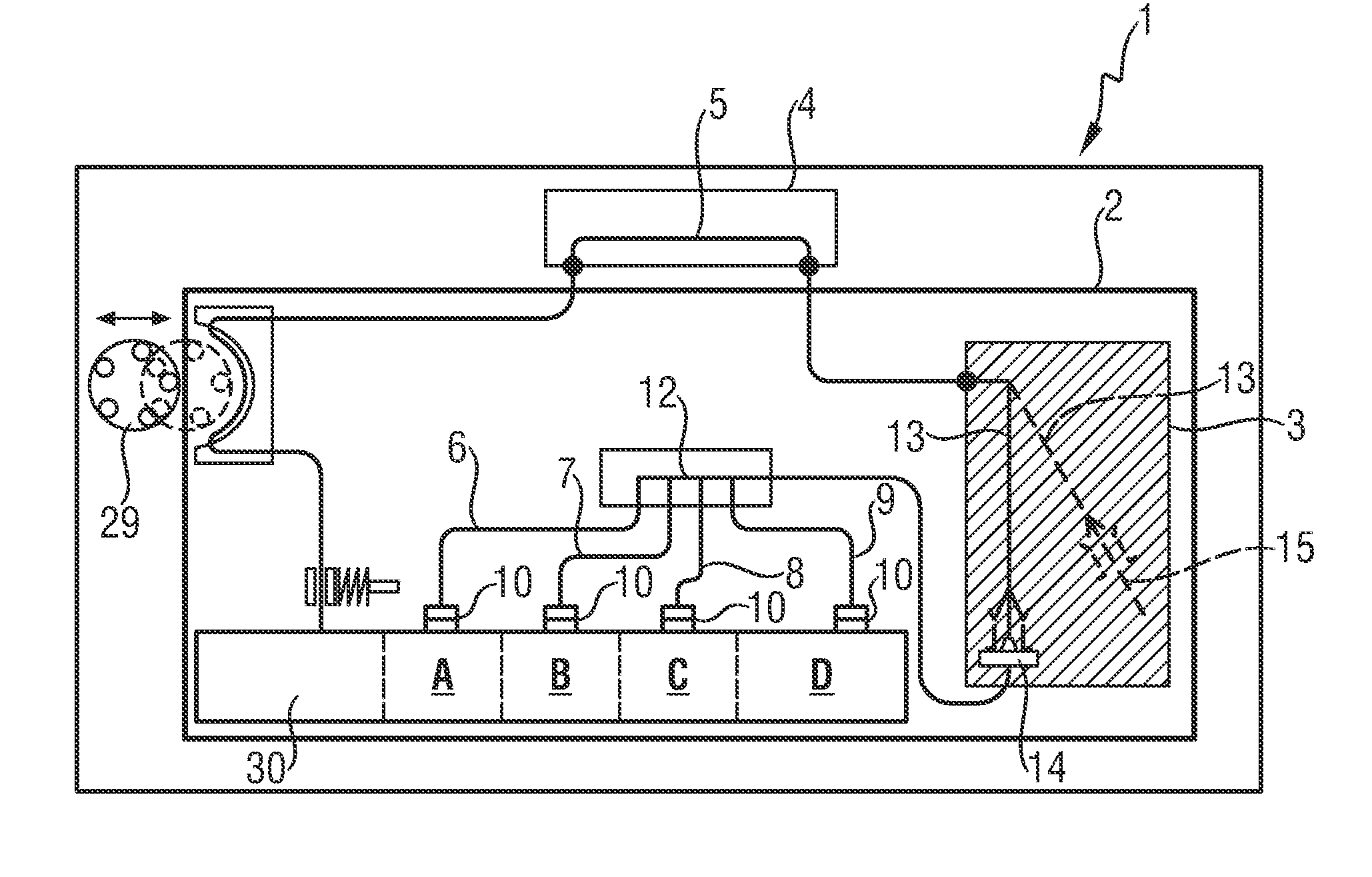
[0051]The procedure shown in table 1 (provided below) starts from an initial state (step 1), in which the fluid lines from the respective bag valve 10 to the measuring chamber 5 are filled with air. All bag valves 10 are in position SG, the hose pump 29 is deactivated and the input unit 13 is in the docking element 14 (posW).
[0052]The packet size, i.e., the amount or volume of fluid from reagent bag A, may be determined by timing or by the signal of monitoring sensors deployed in the line to the measuring chamber 5.
[0053]Optional steps preceding step 1 for initialising the application of the example, which are not further described here, may be provided. For terminating the application of the example, optional steps following steps 1 to 8 are possible (again not further described).
TABLE 1ValveValvePosition ofpositionpositionInput unitStepbag Abags B-D13Action1SGSGPosWStandby2SG->SKSGPosWValve at A in ...
example 2
Rinsing and Preparing for Positioning a Sample in the Measuring Chamber
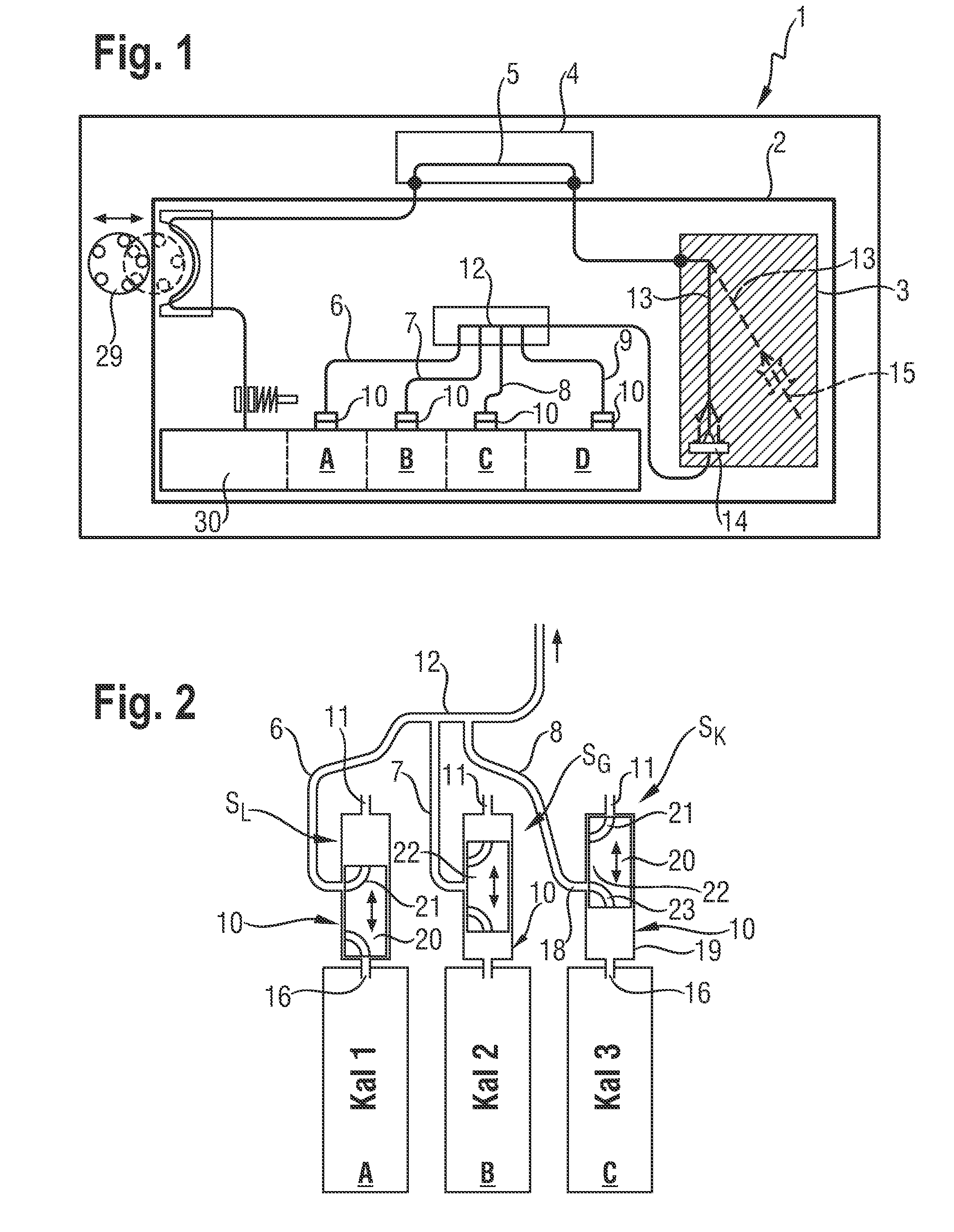
[0054]In one embodiment the multi-way valve of at least one reagent bag containing rinsing, flushing or disinfectant fluid, is alternatingly switched from a first valve position (SK) for sucking in fluid to a second valve position (SL) for sucking in a gaseous medium, such as for example air, thus alternatingly forming fluid and gas packets, which are transported through the line system of the analyzer into the measuring chamber. It has been found that cleaning the measuring chamber by alternatingly flushing it with fluid packets and separating air packets is of particular advantage.
[0055]The procedure shown in table 2 starts from an initial state (step 1), in which the connecting lines from the respective bag valve 10 to the measuring chamber 5 are air-filled. All bag valves 10 are in position SG, the pump 29 is deactivated and the input unit 13 is in the docking element 14 (posW).
TABLE 2ValveValveValvepositionp...
example 3
Partially Filling the Connecting Lines 6 to 9 of Reagent Bags A to D with Fluid
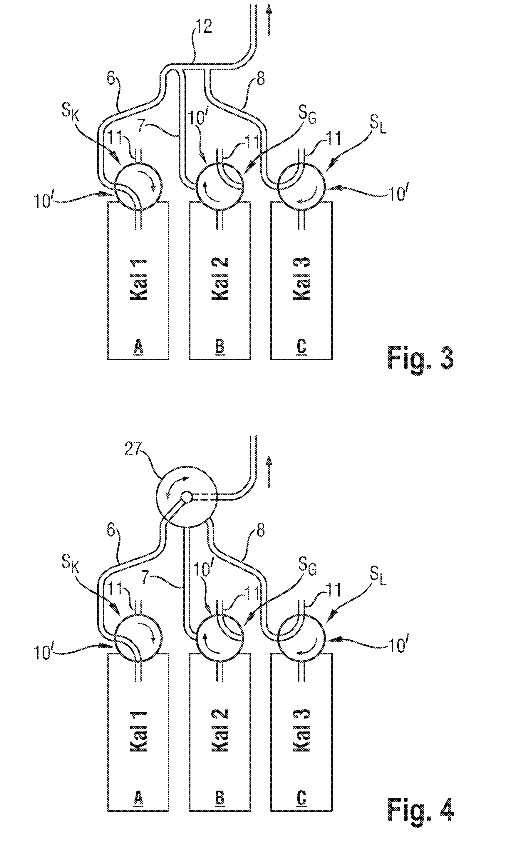
[0057]In the embodiment with a common rail 12 (see FIG. 1 to FIG. 3) it has been found that in the case where fluid, in particular a calibrating fluid containing dissolved gases, is sucked through a connecting line 6 and the common rail 12, contact is established between the flowing fluid and the gas present in the other connecting lines 7, 8, 9, resulting in a concentration change of the gases dissolved in the fluids. This is a disadvantage when calibrating fluids for gas sensors are concerned.
[0058]During transport of fluid and separating gas packets in one embodiment pressure in the gas-containing connecting lines of the reagent bags is first lowered, which in one embodiment by a short-term increase of the rpm of the hose pump 29 provided in the analyzer for fluid transport, and thereafter pressure is raised again, which in one embodiment by reducing the rpm of the hose pump 29, thus bringing it back t...
PUM
 Abstract
Description
Claims
Application Information
 - R&D Engineer
- R&D Manager
- IP Professional
- Industry Leading Data Capabilities
- Powerful AI technology
- Patent DNA Extraction
Browse by: Latest US Patents, China's latest patents, Technical Efficacy Thesaurus, Application Domain, Technology Topic, Popular Technical Reports.
© 2024 PatSnap. All rights reserved.Legal|Privacy policy|Modern Slavery Act Transparency Statement|Sitemap|About US| Contact US: help@patsnap.com