Integrated medical imaging systems

Inactive Publication Date: 2009-07-09
MEDRAD INC.
View PDF42 Cites 43 Cited by
  • Summary
  • Abstract
  • Description
  • Claims
  • Application Information

AI Technical Summary

Benefits of technology

[0032]In several embodiments, the devices, systems and methods of the present invention go beyond the ever expanding communications, control, and processing capacity of the computer and electronic disciplines to facilitate cooperation between independent devices. The devices, systems and methods of

Problems solved by technology

Imaging systems or devices are relatively higher cost capital pieces of equipment.
This separation has also limited the interaction between fluid injectors and imaging systems.
Another factor that has maintained the separation of imagers and injectors is the very different regulatory risks associated with the two products.
While both are in the broad Class II classification in the FDA regulatory structure, the most serious hazard with imagers is overexposure of the patient to the imaging energy, which, while not insignificant, is rarely immediately fatal.
Thus, companies that design and manufacture one product and are familiar with the regulatory requirements and approval processes associated with that product, can be reluctant to add the regulatory hurdles and risk of the other product.
This is difficult to move around the room and can get into the way of patient or operator access to the imager.
One proble

Method used


Image

  • Integrated medical imaging systems
  • Integrated medical imaging systems
  • Integrated medical imaging systems

Examples


Embodiment Construction

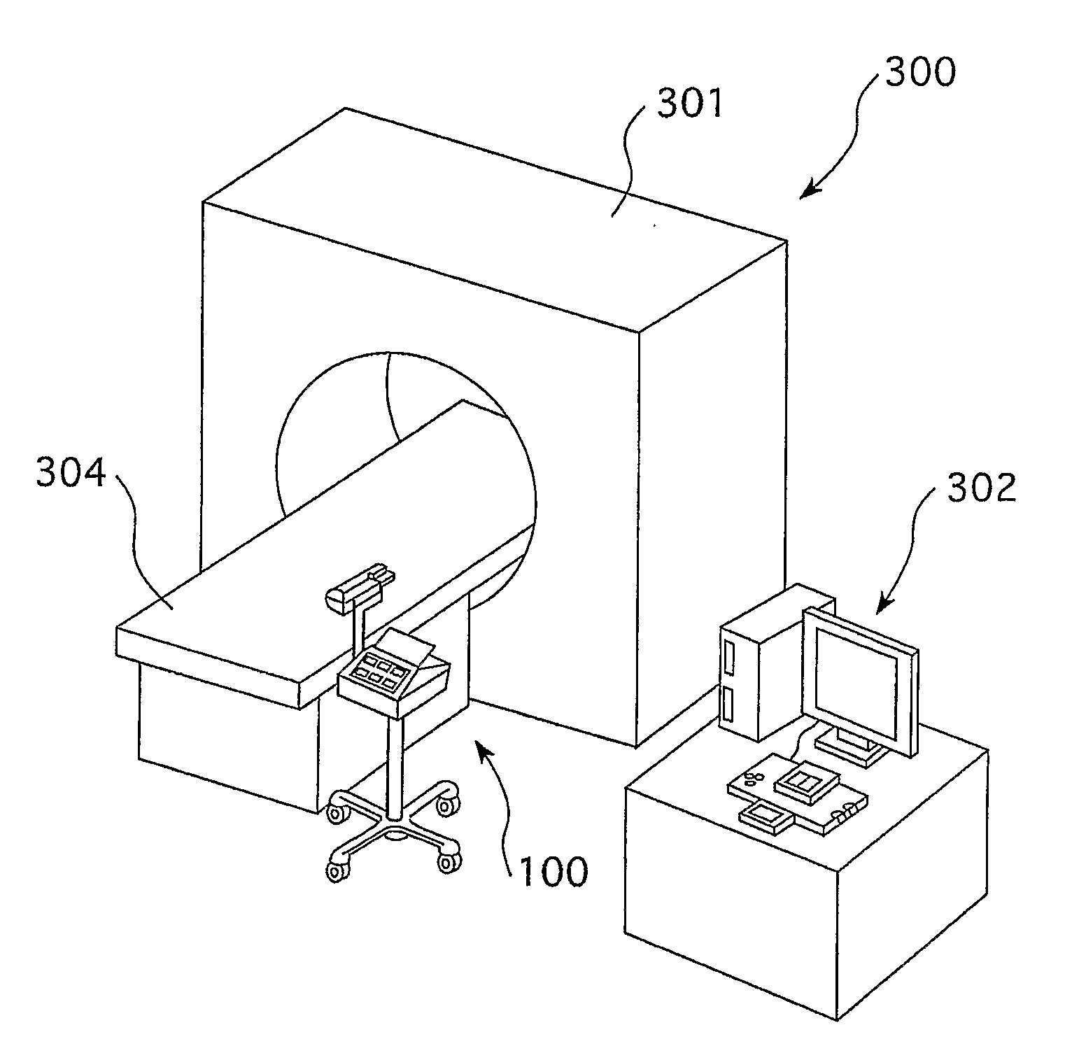
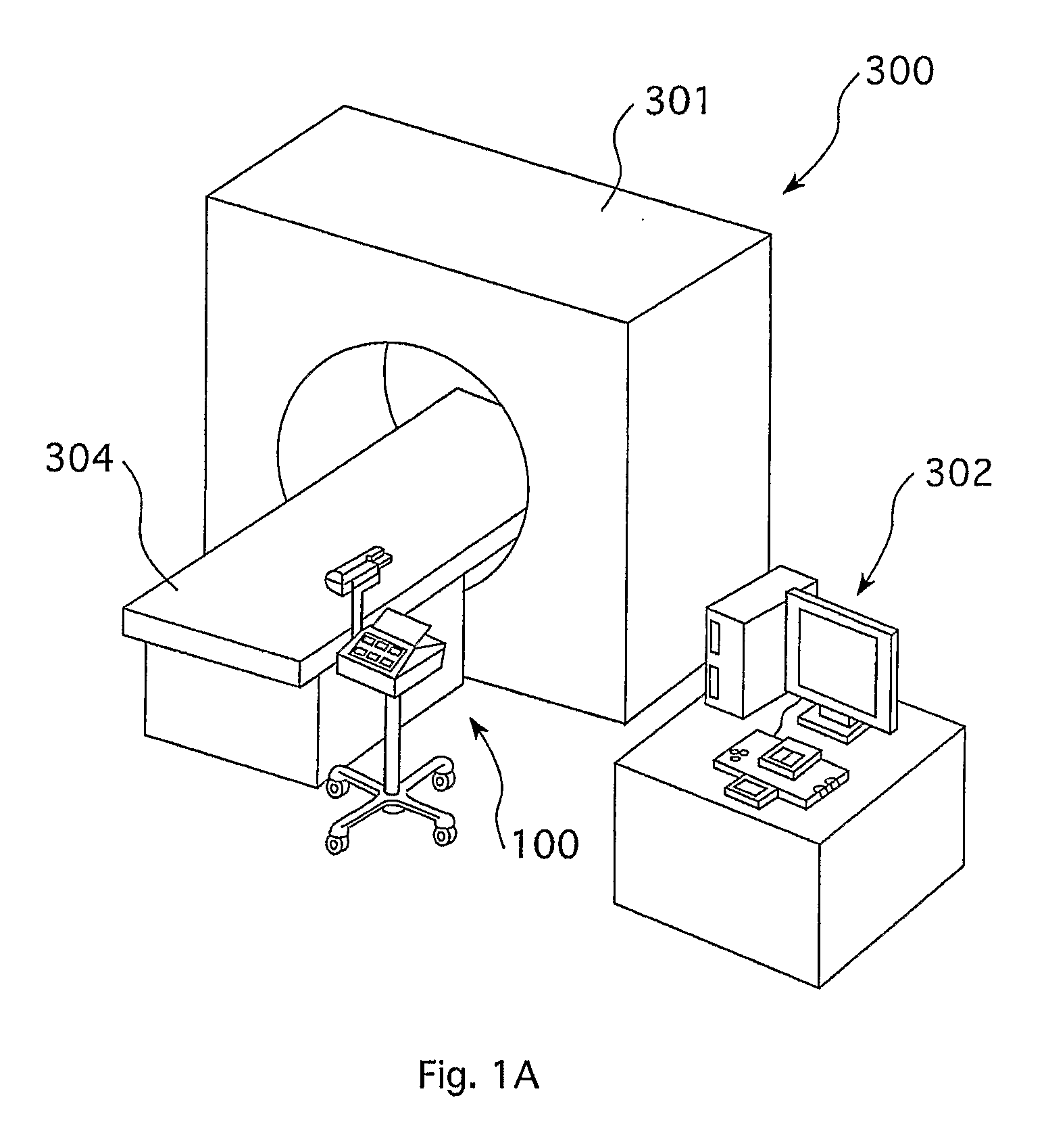
[0052]FIG. 1a illustrates a prior art system based on FIG. 5 of Published U.S. Patent Application No. 2004 / 0199076 A1, illustrating the typical physical and functional separation of an injector 100 from an imager system 300. For ease of understanding, the imager 300 can be considered to be a CT scanner. The image acquisition apparatus 301, commonly called a gantry in CT parlance, contains an X-ray tube that emits X-ray energy as its imaging energy and sensors that measure the X-rays after they have passed through the patient. This information is used by an algorithm, implemented in a computer program in the imager to create an image which can be displayed on the imager user interface 302, commonly called a user console, or sent through the hospital information system or network to other devices, commonly referred to as remote viewing or work stations. The patient is placed on the patient couch, also called a support, positioner, table, or bed 304 and positioned so that the correct r...


PUM


Abstract

An image acquisition system operable to obtain an image of at least a portion of a body, includes an imaging system including at least one energy sensor to measure energy from the body, an image creating system adapted to create an image based at least in part from a signal from the at least one energy sensor, an image display in operative connection with the image creating system and a user interface in operative connection with the image creating system. The image acquisition system further includes a fluid injector system including at least one source of a first fluid, a pressurizing system in operative connection with the source of the first fluid, and a user interface in operative connection with the pressurizing system. The imaging system and the injector system are operatively integrated in at least two of the following and/or other aspects: physical connection, data input via at least one common user interface, displaying of information via at least one common display, electrical connection to at least one common power conditioning system, receipt of common data from at least one patient physiological sensor, at least one common communication port to at least one information system, and a common control system (including any common portion of a control system).

Description

BACKGROUND OF THE INVENTION[0001]The present invention relates generally to integrated medical imaging systems and, particularly, to integrated medical imaging systems in which one or more components of an imaging system are integrated with one or more components of a fluid injector system.[0002]The following information is provided to assist the reader to understand the invention disclosed below and the environment in which it will typically be used. The terms used herein are not intended to be limited to any particular narrow interpretation unless clearly stated otherwise in this document. References set forth herein may facilitate understanding of the present invention or the background of the present invention. The disclosures of all references cited herein are incorporated by reference.[0003]Angiographic injectors for power injecting imaging contrast into the blood vessel were first developed in the 1960's. They were used in conjunction with X-ray imaging equipment to help with...

Claims


Application Information

Patent Timeline
IPC IPC(8): A61B5/05A61B5/00A61M5/145
CPCA61B5/7285A61B6/481A61B8/543A61B6/541A61B8/481A61B6/504
Inventor GRIFFITHS, DAVID M.MISHLER, DAVID A.UBER III, ARTHUR E.
Owner MEDRAD INC.
Why Eureka
Try Eureka