Fuel injector with direct needle control and servo valve support

Active Publication Date: 2009-07-16
ROBERT BOSCH GMBH
View PDF7 Cites 9 Cited by
  • Summary
  • Abstract
  • Description
  • Claims
  • Application Information

AI Technical Summary

Benefits of technology

[0008]To enable a sufficiently long stroke of the injection valve member and thus to enable injecting a sufficiently large quantity of fuel into the combustion chamber of the engine, the control chamber that is defined by the injection valve member and the control piston communicates, through a connecting conduit, with a valve chamber that surrounds the control piston. The valve chamber is a valve chamber of the control valve. As soon as the control valve opens, the valve chamber that surrounds the control piston is in communication with a fuel return. As a result, the further control chamber is pressure-relieved when the control valve is open. The injection valve member can travel a longer distance.
[0010]To enable filling the further control chamber with fuel at system pressure when the control valve is closed, the valve chamber of the control valve, which chamber communicates with the further control chamber via the connecting conduit, communicates with the fuel inlet by means of a throttle element.
[0016]The embodiment in which the housing is made from a material whose coefficient of thermal expansion is equivalent to that of the actuator, and in which between the housing and the actuator a compensating element is received by which a residual error of the coefficient of thermal expansion between the actuator and the housing is compensated for, is especially preferable whenever the control piston is connected directly to the actuator. This is necessary in order to assure a clean closure of the control valve. Any residual error that may occur in the stroke for generating the tightness of the control valve can be compensated for electrically, for example. For that purpose, it is possible to operate the actuator in bipolar fashion, for example.

Problems solved by technology

It is the disadvantage of the fuel injectors known from the prior art, which are actuated by a piezoelectric actuator, that the piezoelectric actuator must be very long in order to attain a sufficiently long travel of the valve piston of the control valve.
This leads to a long structural length of the fuel injector.

Method used


Image

  • Fuel injector with direct needle control and servo valve support
  • Fuel injector with direct needle control and servo valve support
  • Fuel injector with direct needle control and servo valve support

Examples


first embodiment

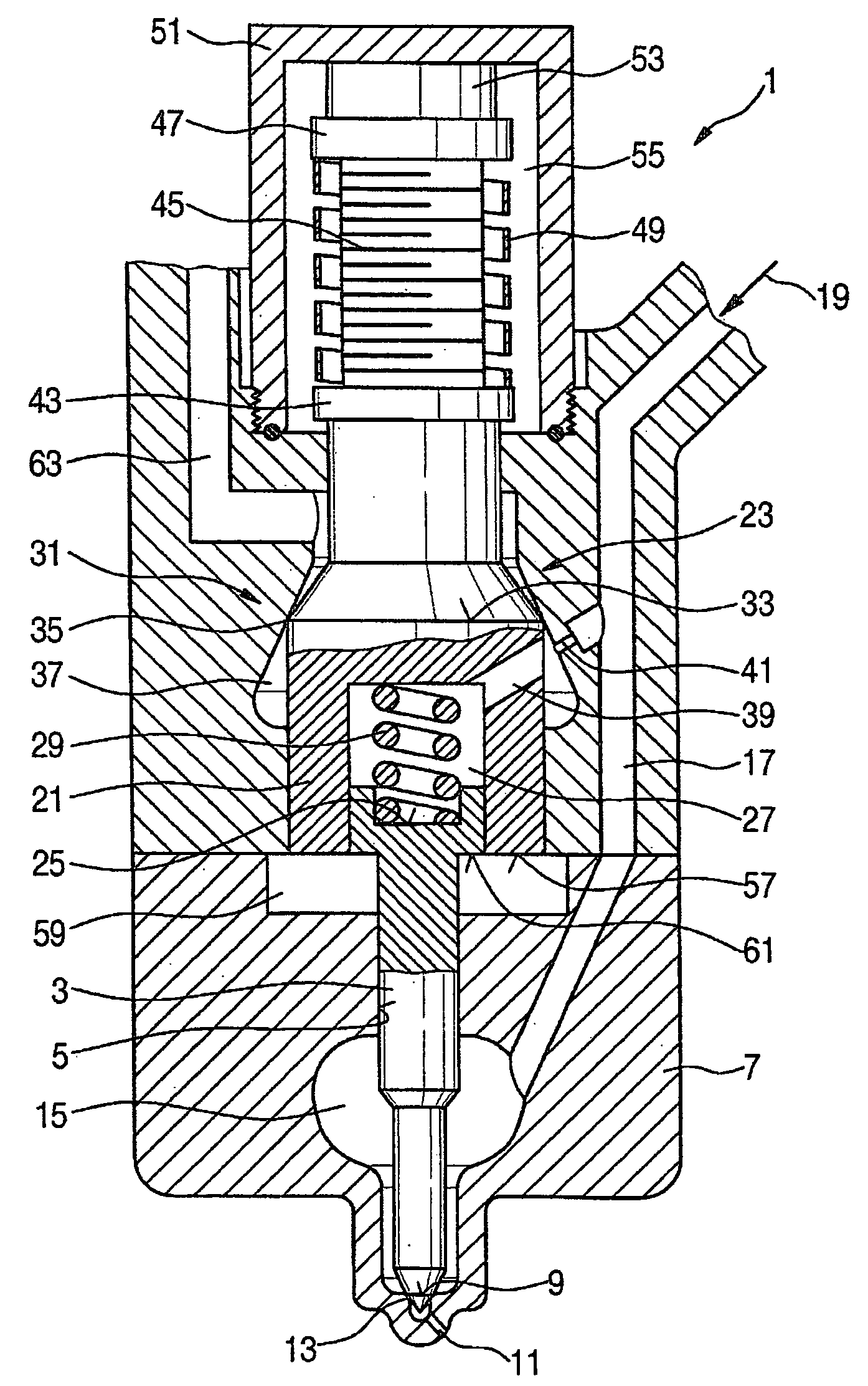
[0022]In FIG. 1, a fuel injector embodied according to the invention is shown in a

[0023]A fuel injector 1 includes an injection valve member 3, which is guided in a guide 5 in a lower housing part 7. A sealing edge 9 is embodied on the injection valve member 3 and when the injection opening 11 is closed is located in a seat 13. In addition to the embodiment shown here, in which the fuel injector 1 has one injection opening 11, it is also possible for more than one injection opening 11 to be provided.

[0024]The injection valve member 3 is surrounded by a nozzle chamber 15. The nozzle chamber 15 communicates via an inflow conduit 17 with a fuel inlet 19. The fuel inlet 19 communicates in turn with a high-pressure reservoir, not shown here, of a common rail system.

[0025]On its end remote from the injection opening 11, the injection valve member 3 has a piston portion, which is guided in an annular portion 21 of a control piston 23. An end face 57, which as a pressure face is exposed to ...

second embodiment

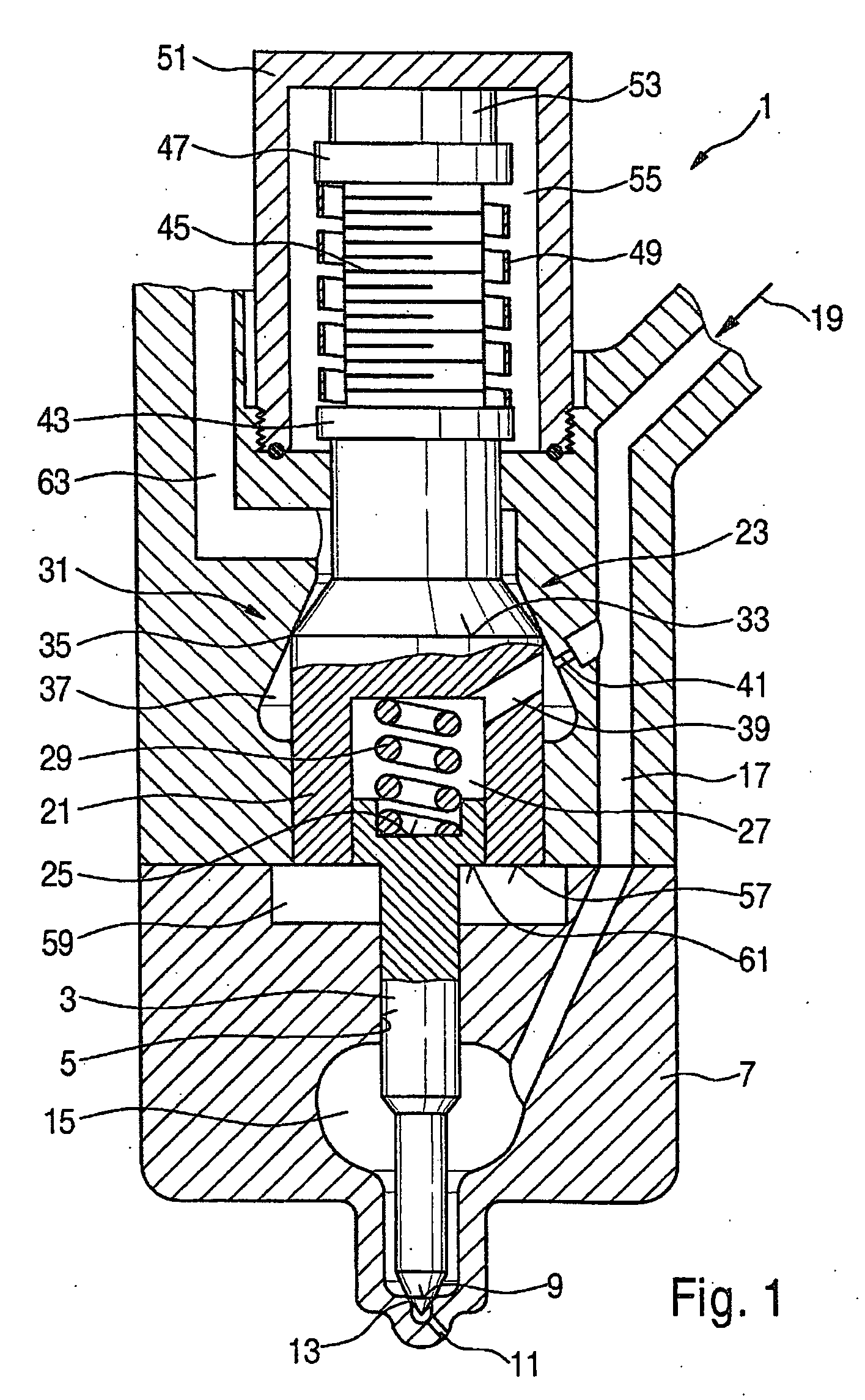
[0035]In FIG. 2, a fuel injector embodied according to the invention is shown in a

[0036]The fuel injector shown in FIG. 2 differs from the fuel injector shown in FIG. 1 in that the control piston 23 is not connected to the actuator 45, but instead, with an upper end face 65, defines a booster chamber 67. On the side diametrically opposite the upper end face 65, the booster chamber 67 is defined by an end face 69 of a booster piston 71. A platelike extension 73, which is connected to the actuator 45, is embodied on the booster piston 71.

[0037]Since the control piston 23 is not connected directly to the actuator 45 and instead, a hydraulic transmission of the motion of the actuator 45 to the control piston 23 is effected, in the embodiment shown in FIG. 2, there is no need to compensate for a stroke error caused by thermal expansion by providing a housing 51 made of material whose coefficient of thermal expansion is equivalent to that of the actuator 45. Compensating for the stroke er...

third embodiment

[0040]FIG. 3 shows a fuel injector embodied according to the invention in a

[0041]Unlike the fuel injector shown in FIG. 2, in the fuel injector shown in FIG. 3, an annular portion 75 is embodied on the piston portion of the injection valve member 3, in which annular portion the control piston 23 is guided. The annular portion 75 and the control piston 23 surround the further control chamber 27. With an end face 77, the annular portion 75 on the piston portion of the injection valve member 3 defines a control chamber 79. A shoulder 81 is also embodied on the control piston 23; it defines the control chamber 79 on the same side as the end face 77 of the annular portion 75. Relative to a third control chamber 83, which communicates with the fuel inlet 19 via the inflow conduit 17, the second control chamber 79 is defined by a ring element 85, which surrounds the annular portion 75 on the injection valve member 3. For that purpose, the ring element 85 is placed with a biting edge 87 aga...


PUM


Abstract

The invention relates to an injector for injecting fuel into a combustion chamber of an internal combustion engine. The injector is actuated by an actuator and is connected to a fuel supply line via which fuel is supplied under system pressure. At least one injection opening can be opened or closed off by an injection valve member, which is activated by a control piston via a control chamber to which the control piston and a piston section of the injection valve member are exposed with respective pressure faces. The control piston is a valve piston of a control valve. The pressure face of the control piston and the pressure face of the piston section of the injection valve member are exposed to the control chamber at the same side. The control piston and the piston section of the injection valve member also enclose a further control chamber which is connected to a fuel return line when the control valve is open and to the fuel supply line when the control valve is closed.

Description

PRIOR ART[0001]The invention is based on an injector for injecting fuel into a combustion chamber of an internal combustion engine as generically defined by the preamble to claim 1.[0002]From German Patent Disclosure DE-A 10 2004 015 744, a fuel injector for injecting fuel into a combustion chamber of an internal combustion engine is known, which has an injector housing that has a fuel inlet which is in communication with a central high-pressure fuel source outside the injector housing and with a pressure chamber inside the injector housing, from which fuel subjected to high pressure is injected as a function of the position of a control valve. The control valve is actuated by means of a piezoelectric actuator. To attain a sufficiently long stroke length for the control valve, a coupling chamber is embodied between the control valve and the piezoelectric actuator. This chamber acts as a hydraulic booster on the valve piston of the control valve.[0003]It is the disadvantage of the fu...

Claims


Application Information

Patent Timeline
IPC IPC(8): F02M43/00
CPCF02M47/027F02M2200/704F02M51/0603
Inventor BOECKING, FRIEDRICH
Owner ROBERT BOSCH GMBH
Why Eureka
Try Eureka