Magnetic fluid seal device

a magnetic fluid and seal technology, applied in the direction of engine seals, mechanical devices, engine components, etc., can solve the problems of low dust generation, high air tightness, and high cost of magnetic fluid seals

Inactive Publication Date: 2009-07-16
EAGLE INDS
View PDF4 Cites 14 Cited by
  • Summary
  • Abstract
  • Description
  • Claims
  • Application Information

AI Technical Summary

Benefits of technology

[0015]According to the magnetic fluid seal device having such constitution, the heating means can be formed by an appropriate heater

Problems solved by technology

The magnetic fluid seal is characterized by high in air tightness, low in dust generation, and low in friction loss torque.
However, in such magnetic fluid seal device, there are cases that the solute such as ferric oxide or so which were maintained by dispersing in a surfactant aggregates after long term storage, long term termination, or when it was not rotated for a long time.
Once the magnetic ultrafine particle as a solute aggregates, the viscosity of the magnetic fluid increases which results to generate an excessive restart torque (starting torque) when rotating the shaft or it may not be able to start.
However, in the conventional seal device which regulates the temperature of the magnetic fluid such as the device described in the reference one, the heater is placed outside of the magnetic fluid seal, therefore the distance between

Method used


Image

  • Magnetic fluid seal device
  • Magnetic fluid seal device
  • Magnetic fluid seal device

Examples


Embodiment Construction

[0021]The embodiment of the present invention will be described using FIG. 1 to FIG. 4B.

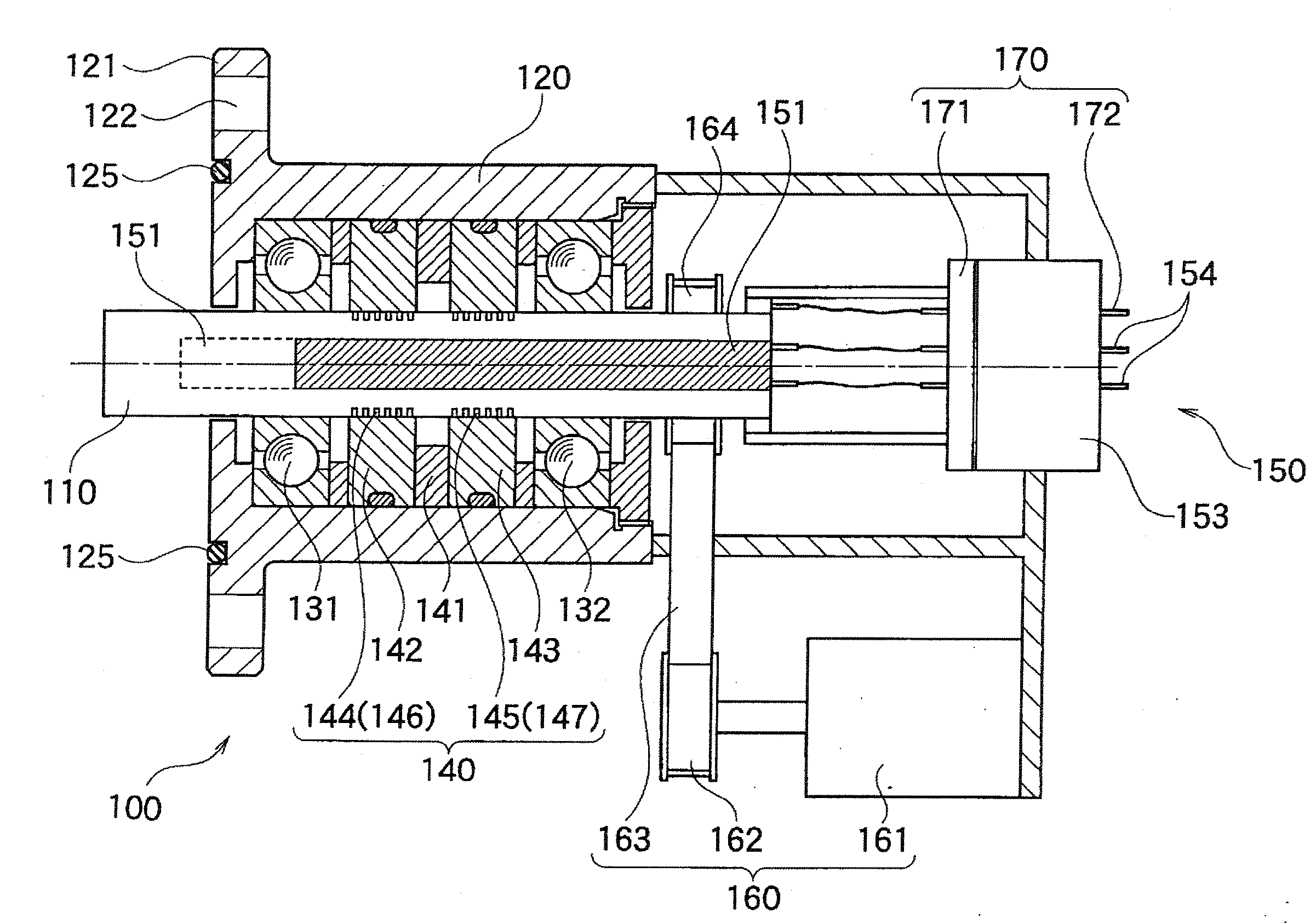
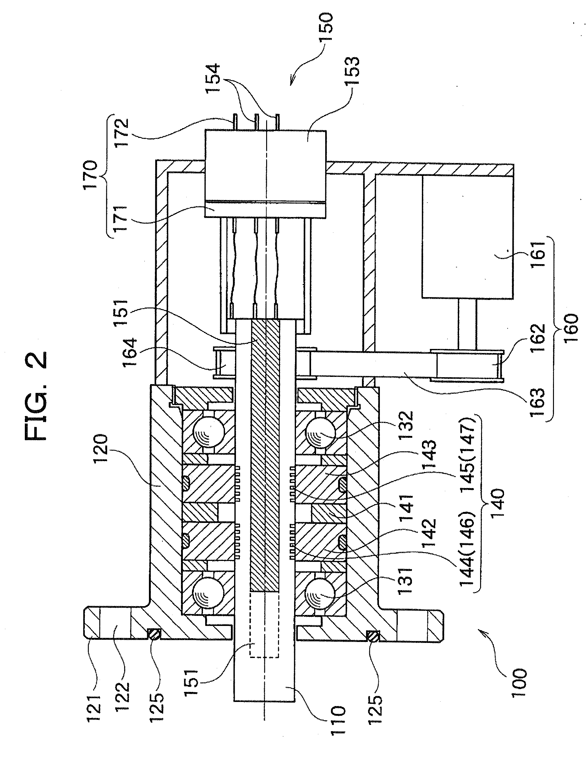
[0022]FIG. 1 is a diagram schematically illustrating the constitution of the wafer processing device 1 as an embodiment of the present invention. FIG. 2 is a cross sectional diagram illustrating the constitution of the magnetic fluid seal device 100 applied in the wafer processing device 1. FIG. 3 is a diagram illustrating the constitution of the controlling system of the heater of the magnetic fluid seal device 100. FIG. 4A and FIG. 4B illustrate the relation between the temperature of the magnetic fluid seal portion and the rotation torque of the shaft.

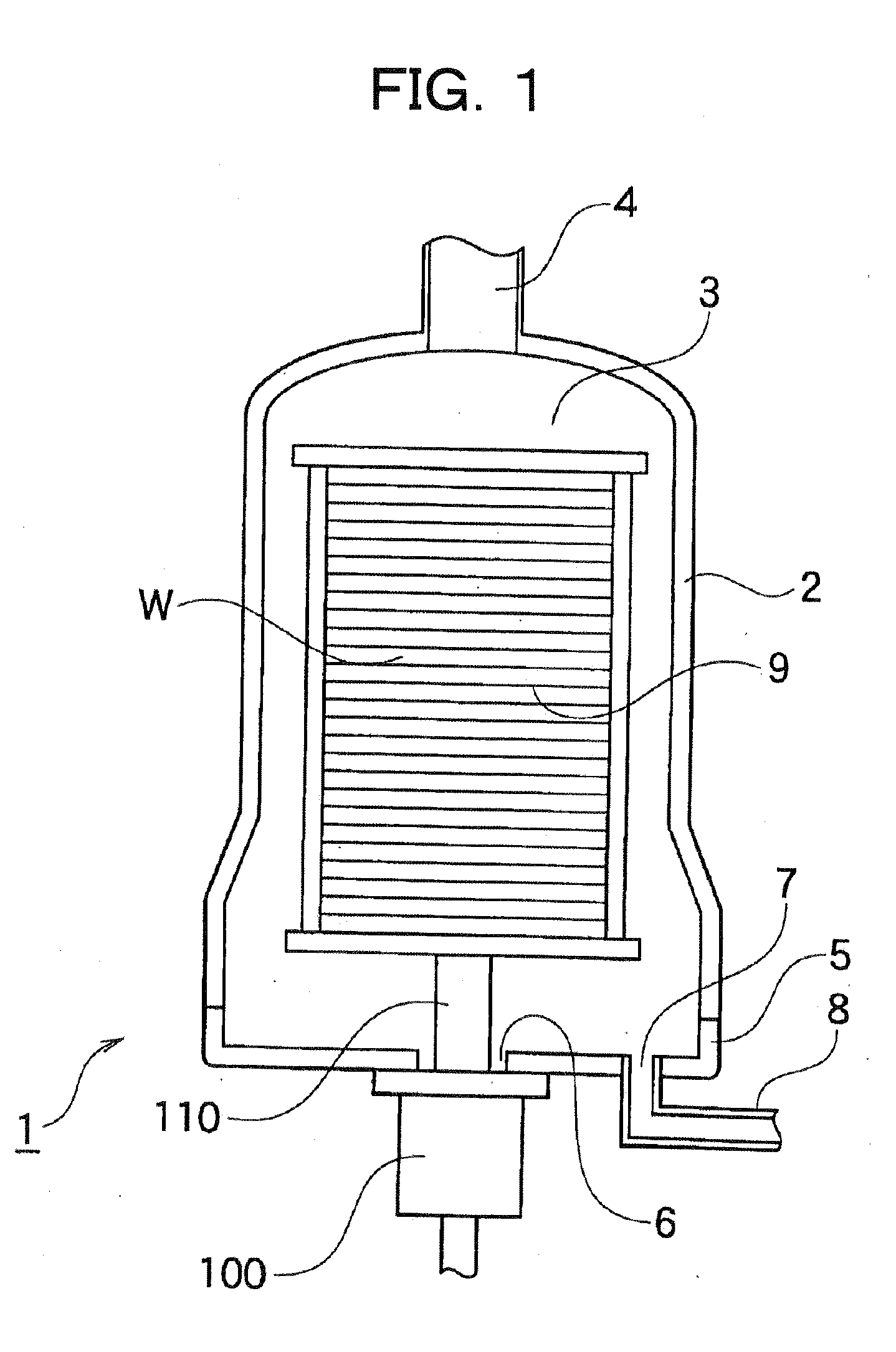
[0023]First, the whole constitution of the wafer processing device 1 will be explained using FIG. 1.

[0024]As show in FIG. 1, the wafer processing device 1 has a constitution wherein the board 9 is supported by shaft 110 of the magnetic fluid seal device contained in the inner container space 3 which is formed by the treating container 2 and base ...


PUM


Abstract

The present invention provides a magnetic fluid seal device which enables to avoid the increase of the torque due to the aggregation of the solute of the magnetic fluid or the condition in which it is unable to start. According to the magnetic fluid seal device of the present invention, the hearer 151 is buried in the area where the magnetic fluid seal portion 140 is position inside the shaft 110. The torque meter 171 detects the rotation torque and the starting torque of the shaft 110, and when it is larger than the standard value, the magnetic fluid seal portion 140 is heated via the heater 151 inside the shaft 110. Thereby, the temperature of the magnetic fluid 146 and 147 rises, the solute of the magnetic fluid 146 and 147 is dispersed which lowers the viscosity thereof, and the rotation torque and the starting torque of the shaft 110 is lowered.

Description

TECHNICAL FIELD[0001]The present invention relates to a magnetic fluid seal device suitable to transfer the movement from outside into a closed space such as chamber or clean room or so.BACKGROUND ART[0002]For example, in a process for producing a semiconductor device, treatment such as oxidation, dispersion or CVD (chemical Vapor Deposition) or so to the semiconductor wafer are performed by holding the wafer in vacuo or in specific gas atmosphere. In many cases, the wafer is placed in a chamber or a container (hereinafter, referred to as a treating chamber), then it is treated by exposing to the atmosphere of the treating chamber by for example rotating or so. Therefore, a treating chamber used for such treatment is required to be highly air tight, as well as to be able to carry a mechanical movement into the treating chamber from outside of the chamber, such as rotation or so of the wafer. As a suitable means to carry the mechanical movement into the treating chamber under the con...

Claims


Application Information

Patent Timeline
IPC IPC(8): F16J15/43
CPCF16J15/43
Inventor KOMINO, MITSUAKIHONDA, SHIGEKI
Owner EAGLE INDS
Why Eureka
Try Eureka