Multilayer Passive Circuit Topology

Active Publication Date: 2009-07-16
NORTHROP GRUMMAN SYST CORP
View PDF4 Cites 21 Cited by
  • Summary
  • Abstract
  • Description
  • Claims
  • Application Information

AI Technical Summary

Problems solved by technology

Typically, high performance lumped filters require significant touch labor for assembly and tuning.
Although providing desirable operations, this approach provides for part of a printed substrate using expensive materials, such as low temperature co-fired ceramic (LTCC).
The complexity of hand tuned filters increases exponentially with the order of

Method used


Image

  • Multilayer Passive Circuit Topology
  • Multilayer Passive Circuit Topology
  • Multilayer Passive Circuit Topology

Examples


Embodiment Construction

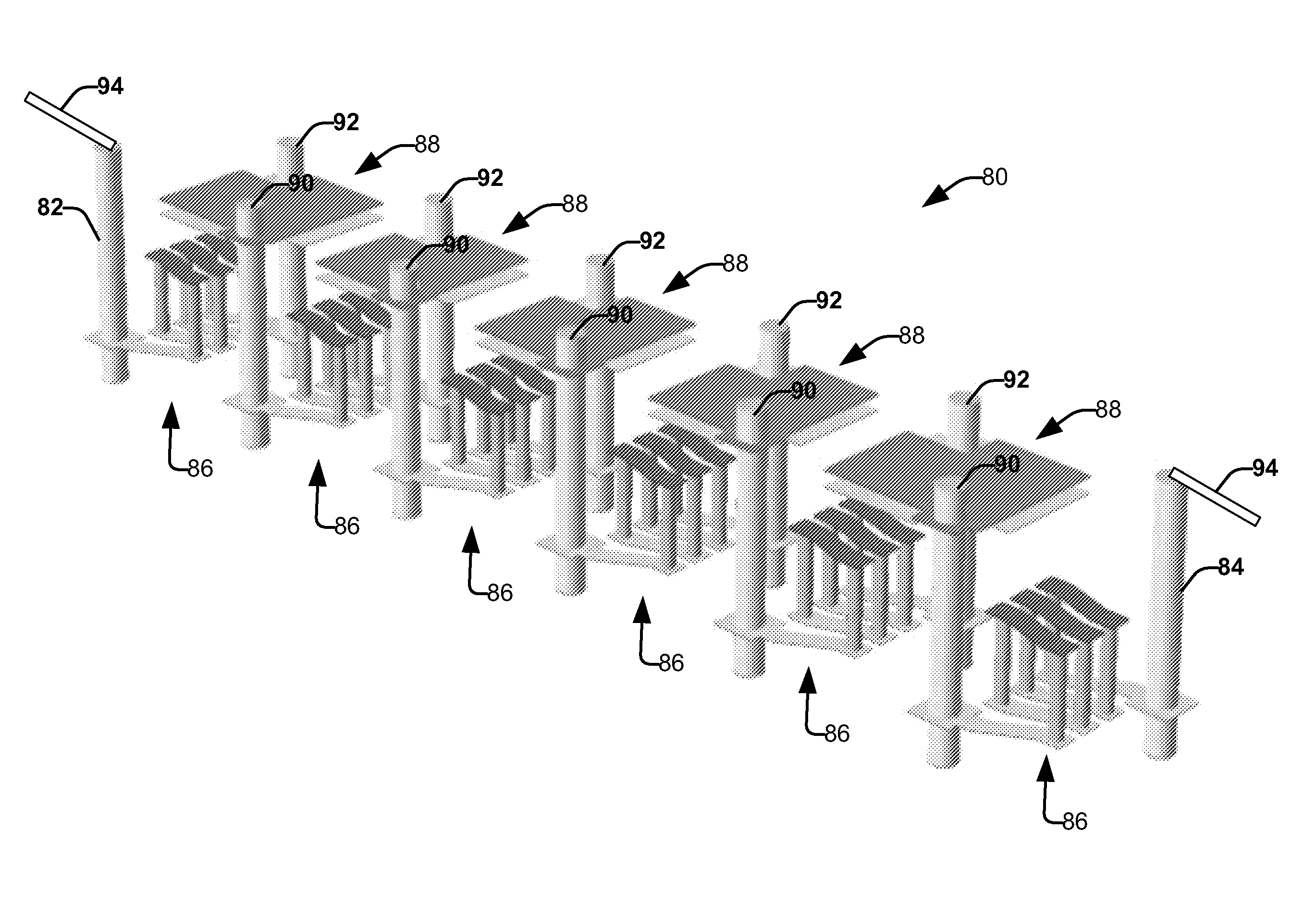
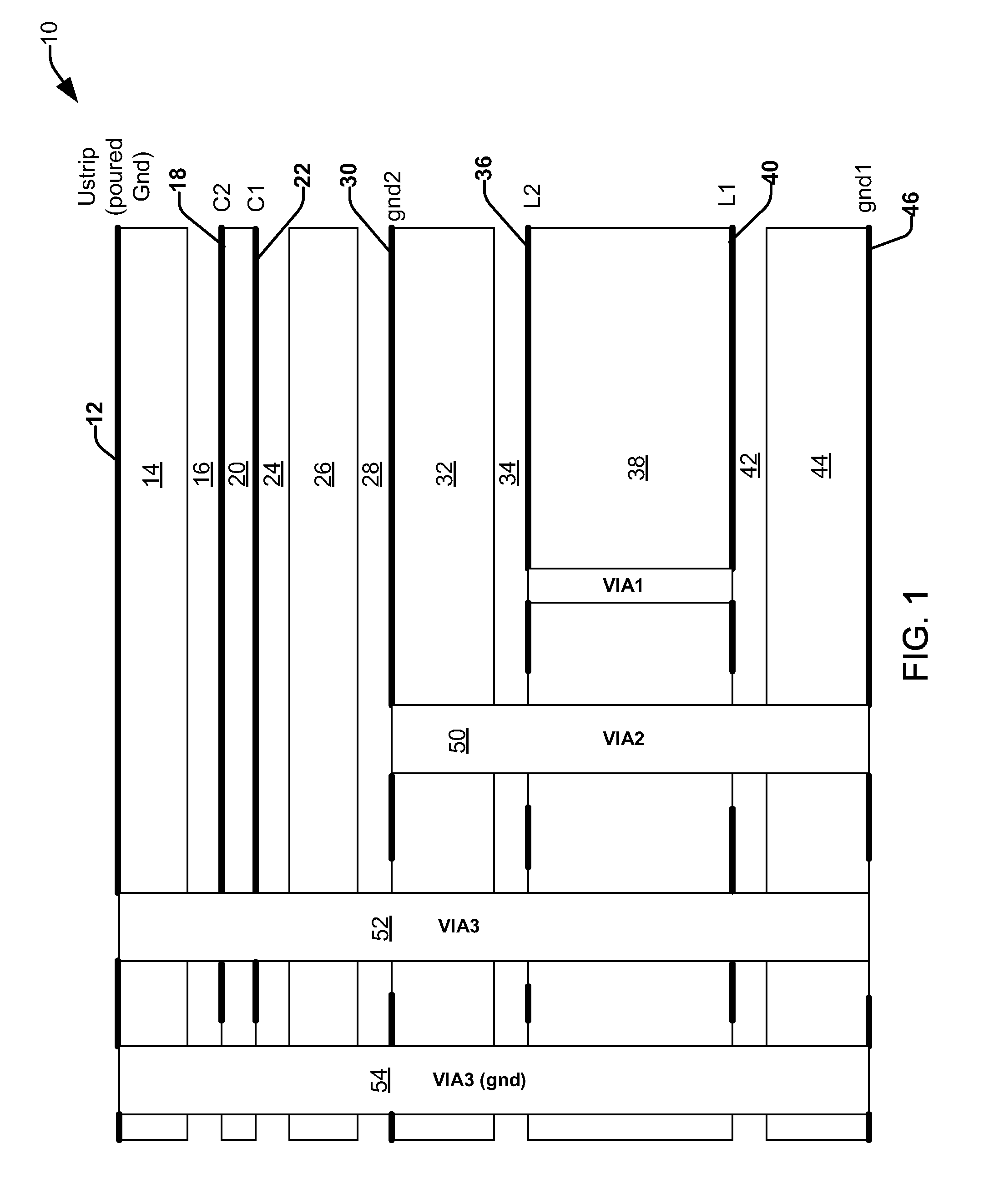
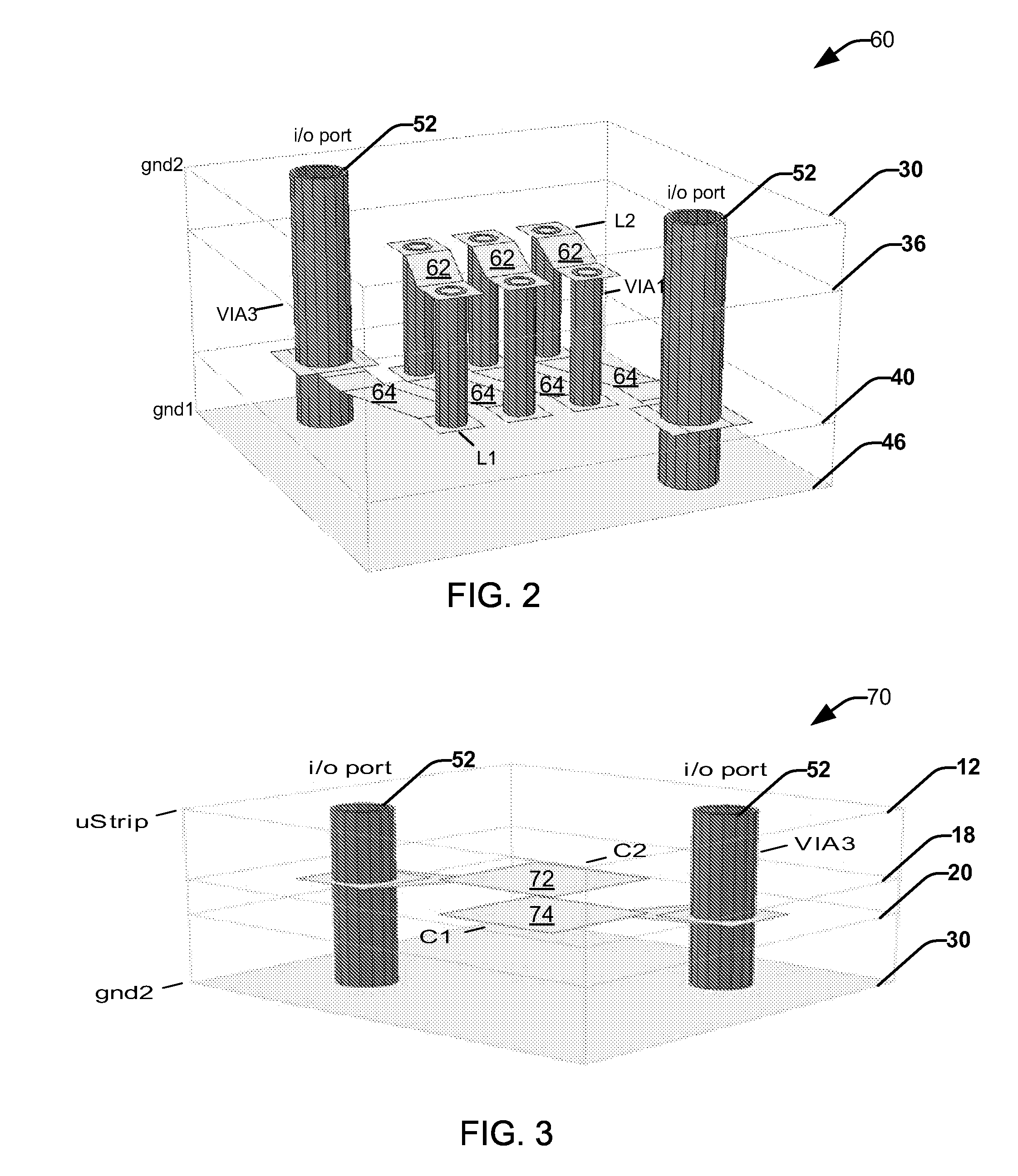
[0015]The present invention relates to a multilayer passive circuit topology supporting any applications requiring precision inductors and capacitors in a low cost material. The multilayer passive circuit topology provides inductor-capacitor (LC) circuits formed from multilayer inductors and multilayer capacitors that can be configured as filters, matching structures, resonators, oscillators or a variety of other LC circuit types. The employment of multilayer passive circuits (e.g., inductors and capacitors), rather than hand-tuned inductors and capacitors, reduces circuit production time, cost, weight and volume. The result is a low cost, highly selective and repeatable multilayer passive structure that can be integrated into a multilayer structure, such as a printed wiring board (PWB) or can be separately surface mounted as a sub-assembly in a manner that minimizes component height, supporting dense electronics packaging. The multilayer passive circuit topology allows for producti...


PUM


Abstract

A multilayer passive circuit topology is disclosed. In one embodiment, a multilayer circuit is provided. The multilayer circuit comprises a multilayer inductor comprising a first set of parallel conductive traces formed on a first layer, a second set of parallel conductive traces formed on a second layer spaced apart from the first layer; and a plurality of vias that connect respective parallel conductive traces from the first and second layer to form inductor windings. The multilayer circuit further comprises a multilayer capacitor connected to an end of the inductor by a coupling via, the capacitor comprising a first conductive plate and a second conductive plate being spaced apart from one another and being formed on different layers.

Description

TECHNICAL FIELD[0001]The present invention relates generally to communications, and more particularly to a multilayer passive circuit topology.BACKGROUND OF THE INVENTION[0002]RF and IF filters are typically used in RF Communications Transceivers (Transmitters and Receivers) for pre- or post-selection of desired signals. Filters are typically sub-octave and enhance receiver (RX) selectivity by rejecting unwanted signals at image frequencies and other points of spurious sensitivity. For a transmitter (TX), filters reject unwanted spurious and harmonics prior to final RF power amplification. Filters are also used at intermediate frequencies in both up / down conversion architecture to reject unwanted signals, as described above.[0003]In a harsh environment, filter response is required to roll-off rapidly outside the band of interest, necessitating a high order filter. In addition, in-band loss must be minimized through the filter to minimize signal degradation. These two requirements dr...

Claims


Application Information

Patent Timeline
IPC IPC(8): H01F27/26H01F5/00H01B13/00
CPCH01F17/0013H01F17/0033H03H2001/0085H05K2201/097H05K1/165H05K3/429H05K2201/09672H05K1/162H03H7/0115
Inventor GOYETTE, WILLIAM R.WINTER, FRANK B.JOHNSTON, ERIC C.PATEL, HARDIK
Owner NORTHROP GRUMMAN SYST CORP
Why Eureka
Try Eureka