Image forming apparatus capable of efficiently and effectively using USB connector

Active Publication Date: 2009-07-16
KONICA MINOLTA BUSINESS TECH INC
View PDF29 Cites 26 Cited by
  • Summary
  • Abstract
  • Description
  • Claims
  • Application Information

AI Technical Summary

Benefits of technology

[0022]In view of the foregoing, an object of the present invention is to provide an image forming apparatus in which USB connectors can efficie

Problems solved by technology

In this respect, when the USB memory scan function is performed for a large amount of documents, the user possibly leaves the spot before the job is completed.
Therefore, it may take a considerable time to perform the conversion of the large amount of documents to the image data and the write operation processing.
However, in the case where the technique disclosed in Japanese Laid-Open Patent Publication No. 2006-140644 is used in the MFP, since the user usually thinks that the print operation will be started when a print button is pressed, the user possibly cannot see the MFP manipulation that the print operation is not started unless the USB memory is extracted.
In this respect, when, in the MFP used in a multi mode environment by multi users, a plurality of USB devices share a connectable environment, there is a limitation in the number of connectors to which the USB devices can be connected, and there is a limitation in the number of connectors which can be used

Method used


Image

  • Image forming apparatus capable of efficiently and effectively using USB connector
  • Image forming apparatus capable of efficiently and effectively using USB connector
  • Image forming apparatus capable of efficiently and effectively using USB connector

Examples


first embodiment

Modification of First Embodiment

[0197]Referring to FIG. 9, the USB device priority screen based on the information in the USB device status management table of FIG. 6 will be described below.

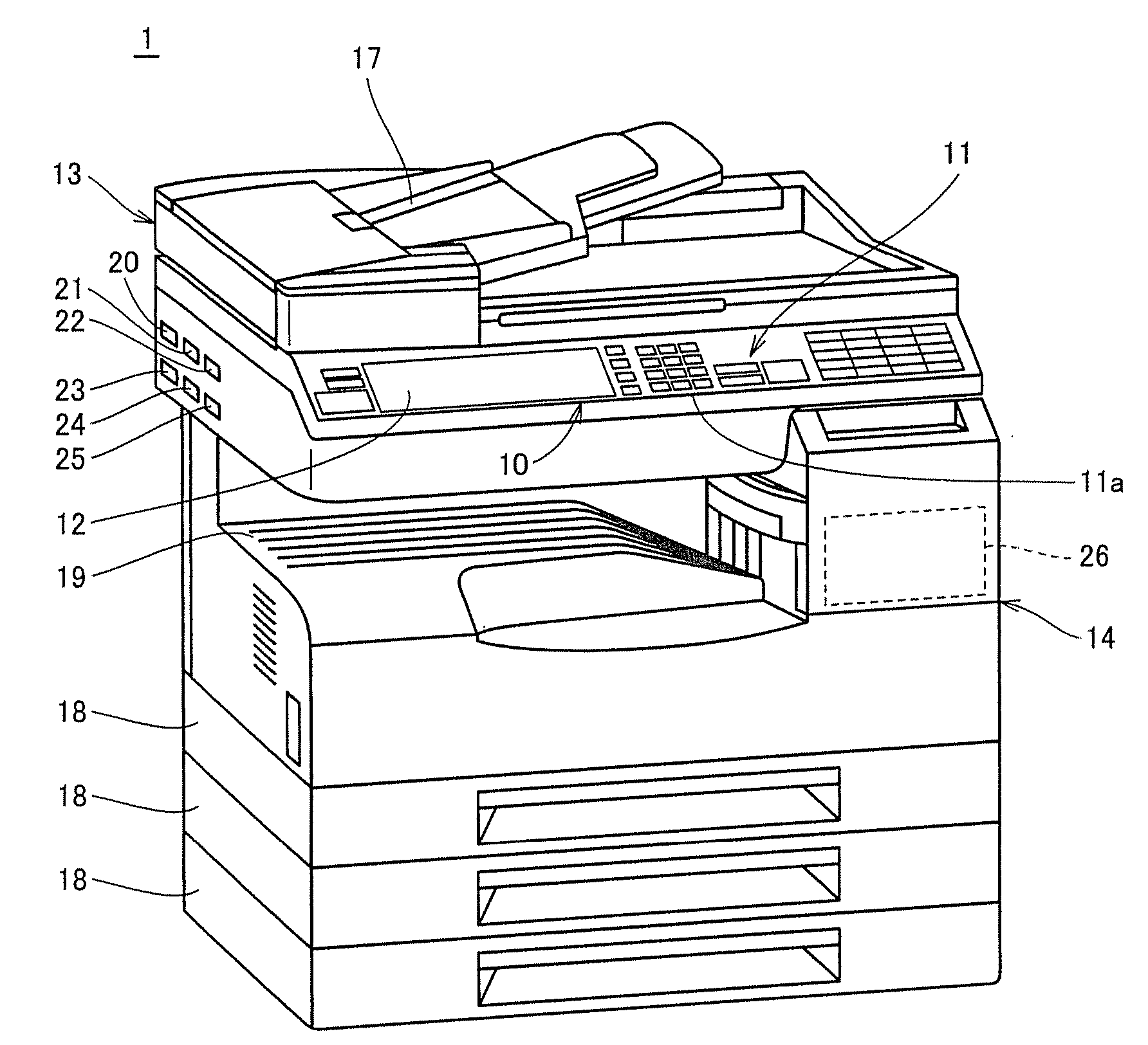
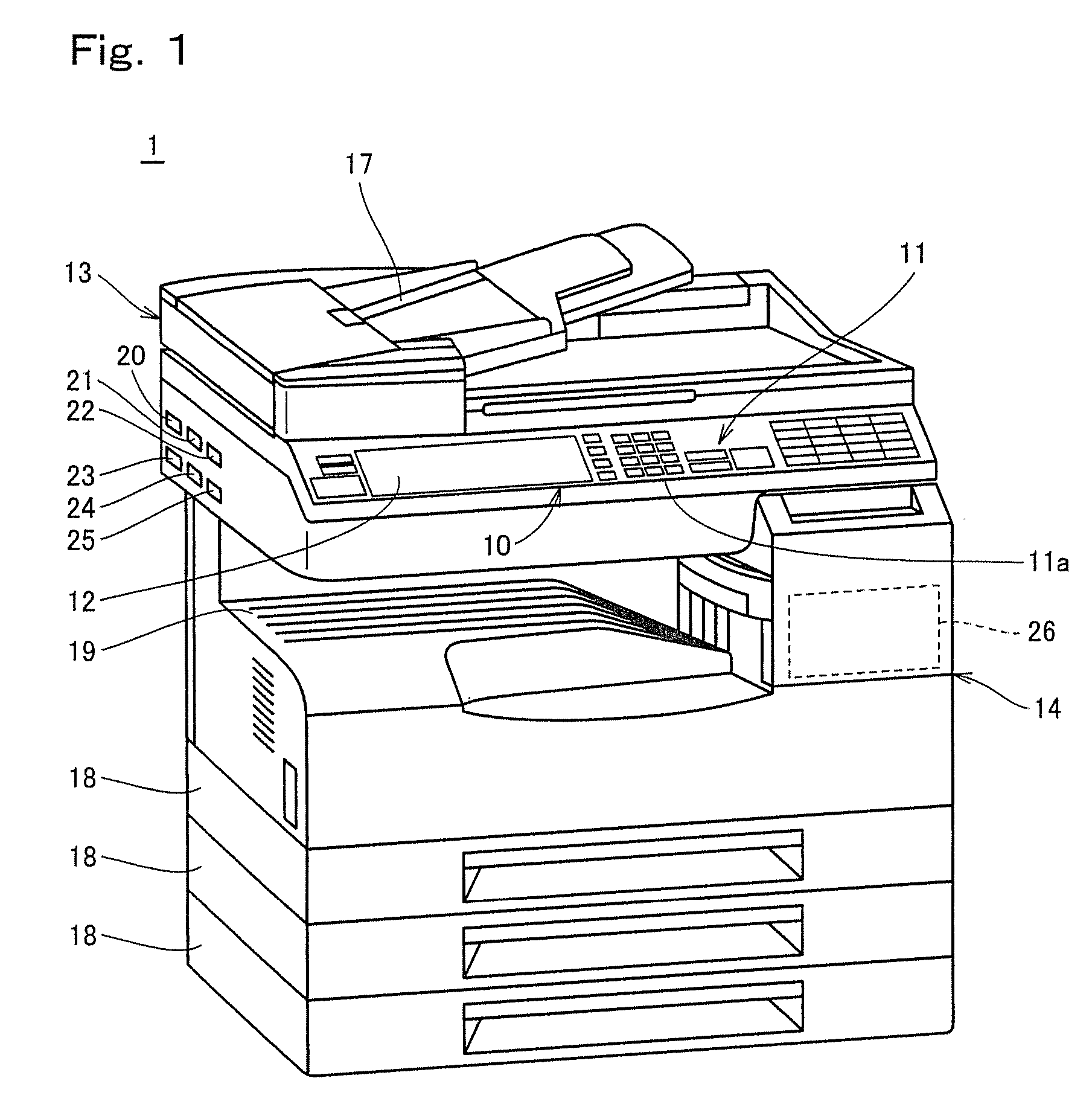
[0198]As shown in FIG. 9, the USB device priority screen is displayed along with a slot model of the USB connector according to shapes of the USB connectors 20 to 25 of FIG. 1, which allows the user to see at a glance which USB device attached to which USB connector in comparison with the configuration of the USB connector in MFP 1. Therefore, user-friendliness is improved. Additionally, the screen display can further prevent the user from mistakenly extracting the USB device in an access state.

Second Embodiment

[0199]In accordance with a second embodiment of the present invention, the case in which ranks 2 to 5 are further classified into sub-ranks to display the priority will be described.

[0200]Specifically, in the ranking determination (Step S3) of FIG. 5, sub-ranking determination is made in ...

second embodiment

Modification of Second Embodiment

[0238]In the above-described second embodiment, ranks 2 to 5 are further classified into sub-ranks to display priority. In a modification of the second embodiment, the case in which rank 6 is classified into sub-ranks will be described.

[0239]Referring to FIG. 16, a flow for performing the sub-ranking determination of rank 6 according to the modification of the second embodiment will be described below,

[0240]Referring to FIG. 16, it is determined whether or not the USB connector is in the access state to which rank 6 is set (Step S60). Specifically, it is determined whether the job state of the USB device attached to the USB connector is the data reading state or the data writing state, including the error state.

[0241]Then, an estimated time until the completion of the job is measured (Step S61). For example, in the case of, e.g., the USB memory (USB HDD) print, the estimated time until the completion of the job is measured based on the type of file f...


PUM


Abstract

It is determined whether or not a USB display button is pressed, and if so determined, a USB device status management table in a USB device status management part is referenced. Ranking determination is made based on information on the USB device status management table. After the ranking determination, priority is set based on the ranking determination result. Then, a USB device priority screen is displayed on a manipulation display of a manipulation panel part.

Description

[0001]This application is based on Japanese Patent Application No. 2008-006040 filed with the Japan Patent Office on Jan. 15, 2008, the entire content of which is hereby incorporated by reference.BACKGROUND OF TEE INVENTION[0002]1. Field of the Invention[0003]The present invention relates to an image forming apparatus, particularly to an image forming apparatus including a USB (Universal Serial Bus) connector attachable to a USB device.[0004]2. Description of the Related Art[0005]Recently, with the widespread use of USB memories, it is frequently seen that a user always carries a USB memory in which document data is stored.[0006]In order to comply with such a case, among MFPs (Multi Function Peripherals) which are one example of the image forming apparatus, an MFP with a so-called USB memory print function and a so-called USB memory scan (also referred to as a Scan To USB memory) function has been increasing in number. With the USB memory print function, documents stored in the USB ...

Claims


Application Information

Patent Timeline
IPC IPC(8): G06K15/00G06F12/14G06F12/00
CPCG03G2215/00092G03G15/502G06K15/00
Inventor ITO, MASAYUKI
Owner KONICA MINOLTA BUSINESS TECH INC
Why Eureka
Try Eureka