Information recording medium and information recording medium evaluation method

Inactive Publication Date: 2009-07-16
PANASONIC CORP
View PDF13 Cites 13 Cited by
  • Summary
  • Abstract
  • Description
  • Claims
  • Application Information

AI Technical Summary

Benefits of technology

[0050]According to the present invention, in an information recording medium such as an optical disc or the like, in an area which has a recording linear density at which the frequency of the shortest mark is sufficiently lower than the OTF cutoff frequency and thus for which the jitter evaluation index is useful, the asymmetry index value based on the 2T amplitude is used for defining the recording quality. Thus, a stable recording medium can be provided. In an area which has a recording linear density at which the frequency of the shortest mark is around, or exceeds, the OTF cutoff frequency and thus for which the jitter evaluation index is not usable and the PR12221ML evaluation index is useful, the β index value based on the ce

Problems solved by technology

However, the recording quality of the information recorded on an optical disc depends on various conditions including the using environment of the drive and the temperature when the information is recorded, as well as various conditions including the type of the optical disc and variance among individual optical disc products.
Thus, unless information is written by laser light of a recording power suitable to the various conditions at the time of information recording, the information cannot be correctly written.
This results in malfunctioning su

Method used


Image

  • Information recording medium and information recording medium evaluation method
  • Information recording medium and information recording medium evaluation method
  • Information recording medium and information recording medium evaluation method

Examples


embodiment 1

[0074]A method for defining the recording quality of a recording medium according to Embodiment 1 of the present invention will be described.

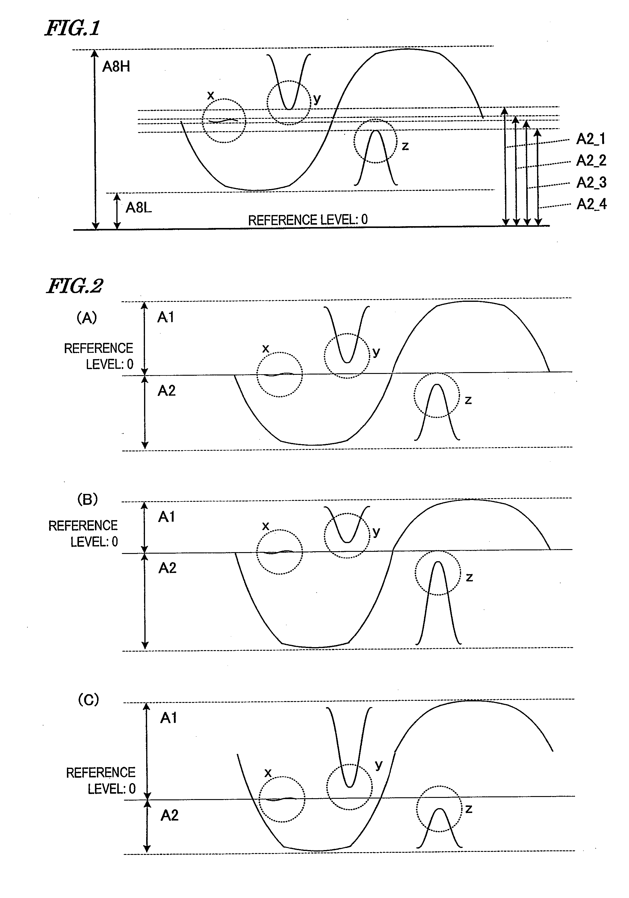
[0075]FIG. 1 shows reproduction signal amplitude levels of the longest mark / space (8T) and the shortest mark / space (2T) shown in FIG. 18. FIG. 1 specifically shows the reproduction signal amplitude levels obtained when reproduction is performed from an area of a BD medium in which recording has been performed at a recording density of 33 GB. The reproduction signal amplitude level of the longest mark / space means an amplitude level of a reproduction signal obtained when a combination of the longest mark and the longest space is reproduced. The reproduction signal amplitude level of the shortest mark / space means an amplitude level of a reproduction signal obtained when a combination of the shortest mark and the shortest space is reproduced.

[0076]With reference to FIG. 1, the reproduction signal amplitude level of the shortest mark / space (2T) in a...

embodiment 2

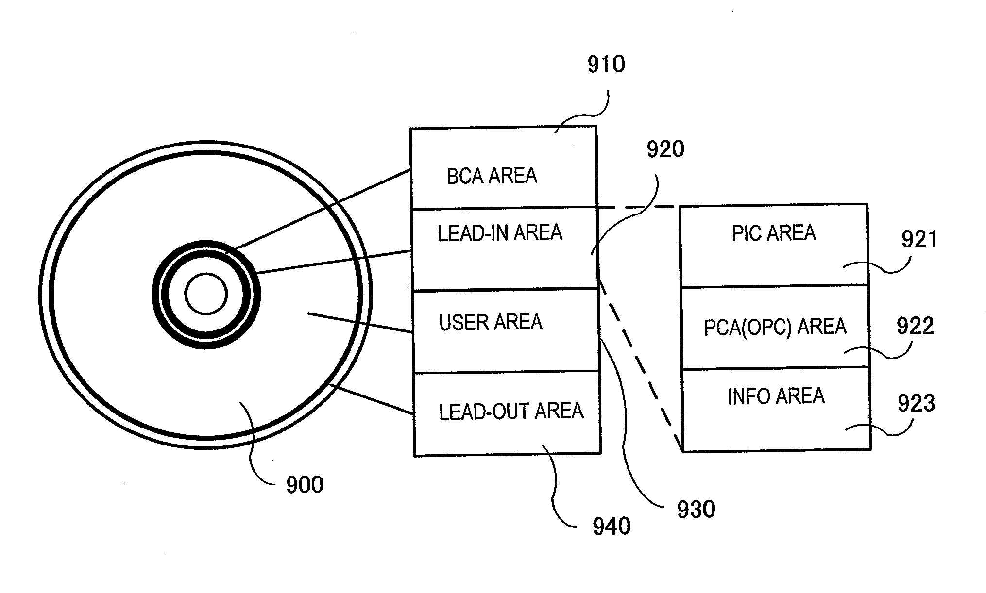
[0103]Now, with reference to FIG. 9 and FIG. 10A, a structure of an optical disc medium and a structure of an optical disc apparatus will be described.

[0104]The optical disc medium 900 includes a recording layer. By forming a recording mark on the recording layer, data is recorded on the optical disc medium 900. On the optical disc medium 900, tracks are formed concentrically.

[0105]The optical disc medium 900 includes a BCA (Burst Cutting Area) area 910, a lead-in area 920, a user area 930 and a lead-out area 940.

[0106]The BCA area 910 has a bar code-like signal pre-recorded therein and includes a unique number for medium identification which is different disc by disc, copyright information, and disc characteristic information. The disc characteristic information includes the number of information recording layers and identification information on the address management method according to the present invention described above.

[0107]The user area 930 is structured to allow the user ...

embodiment 3

[0138]Here, a novel asymmetry measuring method for defining the amplitude center ratio of the mark to be recorded and the space to be within a prescribed range so as to stabilize the compatibility of the optical disc apparatus will be described.

[0139]Asymmetry is defined by the ratio of the center of the reproduction signal amplitude of the shortest mark / space (2T amplitude center), with respect to the center of the reproduction signal amplitude of the longest mark / space (8T amplitude center). Where the frequency of the shortest mark is around, or exceeds, the OTF cutoff frequency, the amplitude is not detected as described above. Due to this problem, it is conventionally difficult to appropriately measure the amplitude center of the appropriate shortest mark / space. According to the present invention, the mark length acting as the reference for measuring the asymmetry is extended in accordance with the recording linear density, and the ratio of the mark length to be recorded and the...


PUM


Abstract

An information recording medium according to the present invention includes an information recording layer on which information is recordable, and is evaluated using an evaluation index which is found based on a ratio of a center of an amplitude of a reproduction signal corresponding to a second shortest mark and a second shortest space, with respect to a center of an amplitude of a reproduction signal corresponding to a longest mark and a longest space.

Description

BACKGROUND OF THE INVENTION[0001]1. Field of the Invention[0002]The present invention relates to a method for defining the amplitude ratio of a recording mark to be recorded on an information recording medium such as an optical disc or the like and a space. In particular, the present invention relates to a method for adaptably changing the defining technique in accordance with the recording linear density so as to control the recording quality of the recording medium to be within a prescribed range and thus to easily make an optical disc apparatus compatible for recording and reproduction.[0003]2. Description of the Related Art[0004]For example, for an optical disc drive (optical disc apparatus) for recording information on write once optical discs (CD-R, DVD-R, BD-R) or recordable optical discs (CD-RW, DVD-RW, BD-RE) using laser light, it is the most important issue to guarantee the recording quality of information recorded on the optical disc. However, the recording quality of the...

Claims


Application Information

Patent Timeline
IPC IPC(8): G11B7/26
CPCG11B7/00736G11B7/1267G11B20/10009G11B2220/2541G11B20/1816G11B2220/215G11B20/10324G11B7/007G11B7/004
Inventor MIYASHITA, HARUMITSUNAKATA, KOHEI
Owner PANASONIC CORP
Why Eureka
Try Eureka