
Digital radio systems and methods

a digital radio and radio system technology, applied in the field of digital radio systems, can solve problems such as limiting storage to caches, and achieve the effect of improving user-interface technology

Active Publication Date: 2009-07-16
3D RADIO
View PDF97 Cites 19 Cited by
  • Summary
  • Abstract
  • Description
  • Claims
  • Application Information

AI Technical Summary

Benefits of technology

[0005]According to the principles of the invention, systems and methods are described for providi

Problems solved by technology

Or, for example, it may limit storage to a cache within the processor chip).

Method used


Image

  • Digital radio systems and methods
  • Digital radio systems and methods
  • Digital radio systems and methods

Examples


Embodiment Construction

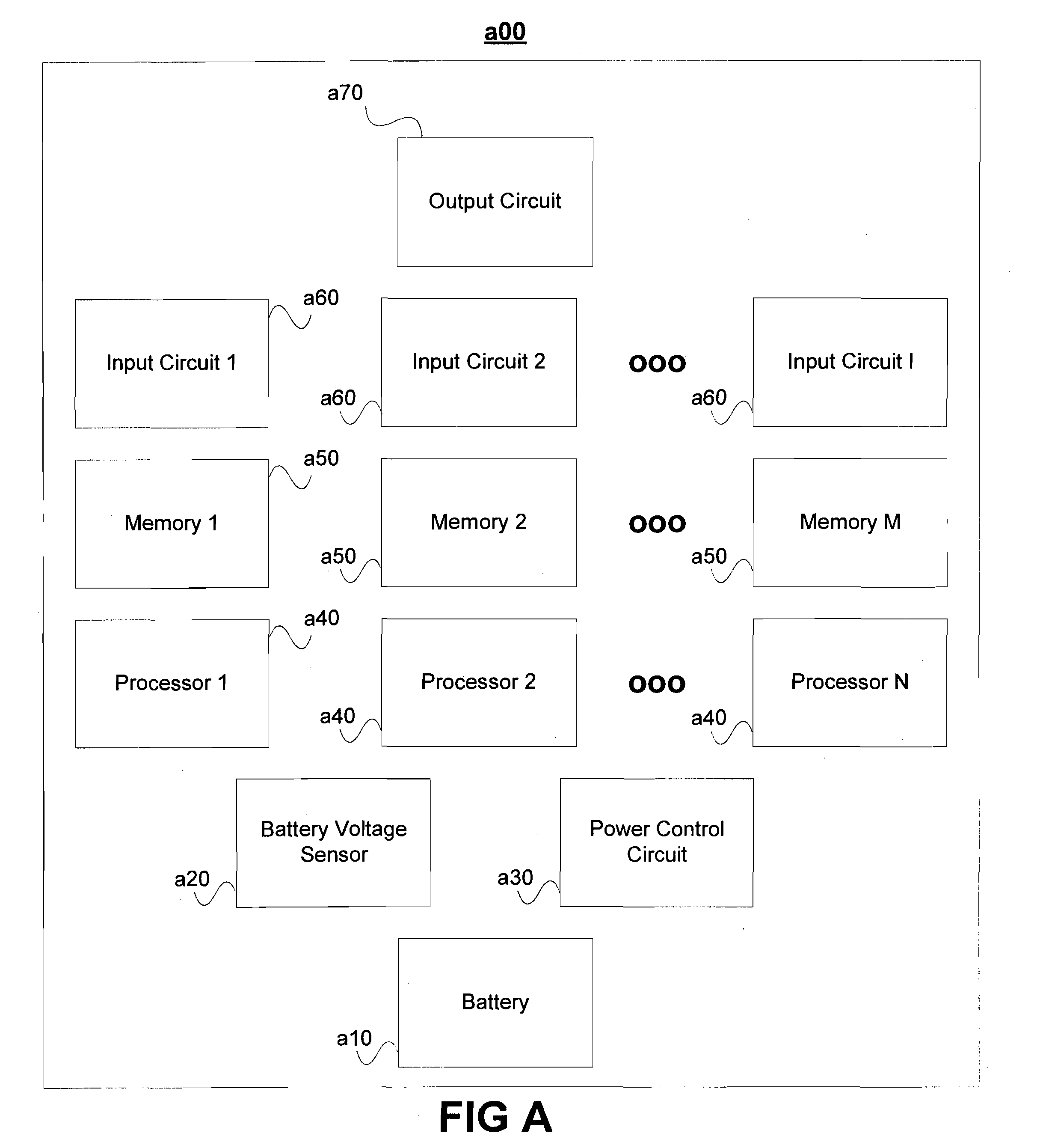
[0015]FIG. A illustrates a block diagram of a multi-channel radio system a00 with a power-control feature. System a00 may be, for example, part of a car stereo; alternatively, it may be a hand-held portable device. System a00 receives power from battery a10. Optionally, system a00 may include battery voltage sensor a20, or another circuit for monitoring the current status of the battery and determining or estimating the amount of battery life remaining. Power control circuit a30, which may also be implemented partially in software, may use monitored information from battery voltage sensor a20, user settings, and other information to control power to various circuits within system a00.

[0016]With further reference to Fig. A, system a00, as shown, includes one or more processors a40. In one embodiment, processor a40 provides computation control capabilities for the power control circuit a30. In particular, processors a40 provide functions related to the multi-channel radio. For example...


PUM


Abstract

A system, apparatus, method, and media directed to power control in the field of digital radio systems are provided. For example, an apparatus, method, or medium can be implemented to enter a radio into lower power mode, store radio programming with reduced functionality, and resume normal power mode.

Description

CROSS-REFERENCE TO RELATED APPLICATIONS[0001]This application claims the benefit of U.S. Provisional Patent Application No. 61 / 019,101, filed Jan. 4, 2008 entitled “Digital Radio Power Control Features” which is incorporated in its entirety by reference as if fully set forth herein.[0002]This application is related to multi-tuner radio systems and methods such as those described in U.S. Pat. No. 7,171,174, U.S. Pat. No. 7,343,141, U.S. patent application Ser. No. 12 / 033,616, and U.S. Pat. No. 11,609,512, which are hereby explicitly incorporated by reference herein in their entirety such as with respect to specific implementations of such systems and methods.BACKGROUND[0003]Systems and methods of the invention are directed in general to towards digital radio systems, and more specifically related to multi-tuner digital radio systems such as power management for multi-tuner radio systems.[0004]Managing power usage of multi-tuner radio systems such as portable devices or those implemen...

Claims


Application Information

Patent Timeline
IPC IPC(8): H04L27/08H04M1/72442H04M1/72448
CPCH04N21/4436Y02B60/1278H04N5/4401Y02B60/50H04W52/028H04H40/09H04H20/62G06F1/3212G06F1/324G06F1/3275G06F1/3287Y02D10/00Y02D30/70G06Q30/0251H04B5/72H04H20/71H04H60/35H04H60/74H04W4/48H04W4/40H04N21/426H04M1/72442H04M1/72448H04M1/6091
Inventor ELLIS, MICHAEL D.
Owner 3D RADIO
Learn More