
Lithium-Ion secondary battery

a secondary battery and lithium-ion technology, applied in secondary cell servicing/maintenance, cell components, sustainable manufacturing/processing, etc., can solve the problems of unidentical capacity, unbalanced cell pack, unbalanced discharge and charge rate, over-charge or over-charge, etc., to achieve high capacity, reduce cathode cost, and improve chemistry characteristics

Inactive Publication Date: 2009-07-16
BOSTON POWER INC
View PDF58 Cites 39 Cited by
  • Summary
  • Abstract
  • Description
  • Claims
  • Application Information

AI Technical Summary

Benefits of technology

"The present invention is directed to an active cathode material for a lithium-ion battery that includes a mixture of electrode materials. The mixture includes at least one of a lithium cobaltate and a lithium nickelate, and at least one of a manganate spinel and an olivine compound. The manganate spinel is represented by an empirical formula of Li(1+x1)(Mn1−y1A′y2)2−x2Oz1. The active cathode material has improved performance and capacity as compared to conventional cathode materials. The invention also includes a lithium-ion battery that uses this active cathode material and a battery pack that includes the active cathode material."

Problems solved by technology

However, when cells are aged and cycled, cells tend to deviate from the initial ideal conditions, resulting in an unbalanced cell pack (e.g., unidentical capacity, impedance, discharge and charge rate).
This unbalance among the cells may cause over-charge or over-discharge during normal operation of the rechargeable batteries, and in turn can impose safety concerns, such as explosion (i.e., rapid gas release and possibility for fire).
On the other hand, with higher charging voltage, the cell is less safe.
In general, it is a challenge for LiCoO2-based lithium-ion cells to have a high capacity, for example higher than about 3 Ah due to a high safety concern.
However, this will lower the cell capacity, and in turn lower cell energy density.
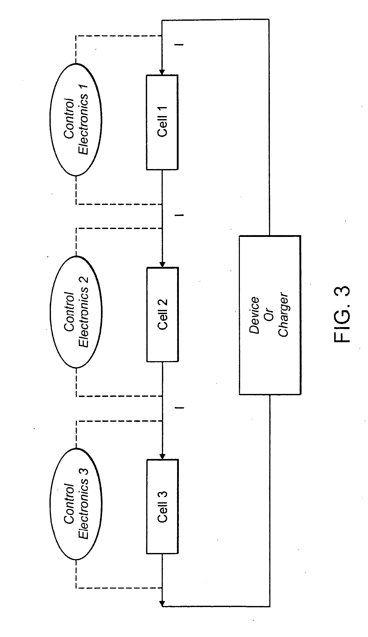
However, the increase in the number of cells can result in increased probability of unbalance among the cells, which can cause over-charge or over-discharge during normal operation, as discussed above.
It is generally believed that it is not safe to use LiCoO2 in a larger cell than the 18650 cell because of a safety concern associated with LiCoO2.

Method used


Image

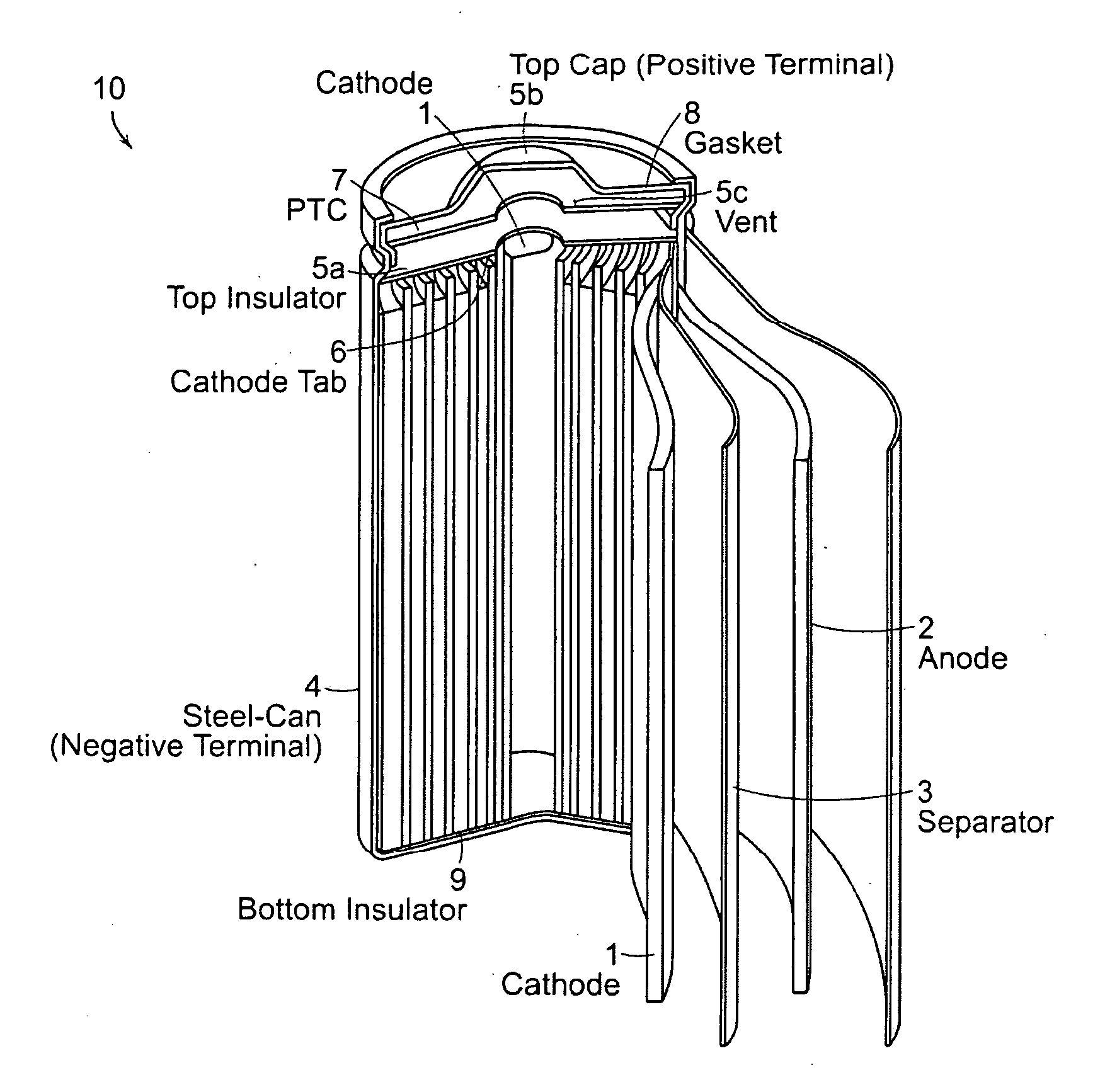
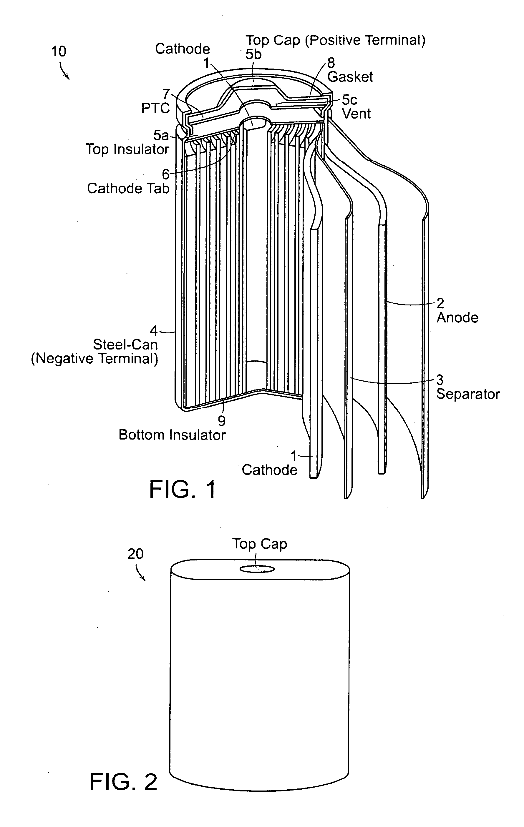
  • Lithium-Ion secondary battery
  • Lithium-Ion secondary battery
  • Lithium-Ion secondary battery

Examples


example 4

An Oblong Cell with High Capacity Having an Active Cathode Material Including LiCoO2 / LiMn2O4

[0133]94 wt. % mixed cathode with a weight ratio of 70:30 for LiCoO2:LiMn2O4, 3 wt. % of carbon black and 3 wt. % of PVDF were mixed in NMP under stirring. The electrode slurry was coated onto a 15 micrometer thick Al current collector. The Al current collector had a dimension of width of 56 mm and length of 1568 mm. The slurry was coated on both sides of the Al current collector. The coating length was 1510 and 1430 mm for side 1 and side 2. The process media NMP was removed by heating the coated electrode at 150° C. for a few minutes. The electrode was pressed to control the coated density. The 2-side coating was identical in every aspect. The thickness of the total electrode was 140 micrometers. The composite cathode density was 3.6 g / cc. Two Al tabs with about a width of 3 mm, length of 55 mm and thickness of 0.2 mm were welded onto the uncoated Al current collector. 93 wt. % of graphite...

example 5a

Prophetic Example

A Cell with an Active Cathode Material Including LiCoO2 / LiMn1.9Al0.1O4

[0137]In this example, a prismatic cell with an active cathode material including LiCoO2 / LiMn1.9Al0.1O4 is designed. This cell can be made by a similar procedure as described above in Example 4. For this example, the cathode mix includes 94 wt. % of mixed cathode with a weight ratio of 70:30 for LiCoO2:LiMn1.9Al0.1O4, 3 wt. % of carbon black and 3 wt. % of PVDF. The electrode slurry is coated onto a 15 micrometer thick Al current collector. The Al current collector has a dimension of width of 56 mm and length of 1913 mm. The slurry is coated on both sides of the Al current collector. The coating length is 1913 and 1799 mm for side 1 and side 2. The process media NMP is removed by heating the coated electrode at 150° C. for a few minutes. The electrode is pressed to control the porosity of 25% volume. The 2-side coating is identical in every aspect. The thickness of the single coating layer is 50 ...

example 5b

Prophetic Example

A Cell with an Active Cathode Material Including LiCoO2 / LiMn1.9Al0.14 / LiNi0.8Al0.05Cu0.15O2

[0142]In this example, a prismatic cell with an active cathode material including LiCoO2 / LiMn1.9Al0.1O4 / LiNi0.8Al0.5Co0.15O2 is designed. This cell can be made by a similar procedure as described above in Example 4.

[0143]94 wt. % of mixed cathode with a weight ratio of 10:50:40 for LiCoO2: LiMn1.9Al0.1O4:LiNi0.8Al0.05Co0.15O2, 3 wt. % of carbon black and 3 wt. % of PVDF are mixed in NMP under stirring. The electrode slurry is coated onto a 15 micrometer thick Al current collector. The Al current collector has a dimension of width of 56 mm and length of 1913 mm. The slurry is coated on both sides of the Al current collector. The coating length is 1913 and 1799 mm for side 1 and side 2. The process media NMP is removed by heat the coated electrode at 150° C. for a few minutes. The electrode is pressed to control the porosity of 25% volume. The 2-side coating is identical in eve...


PUM

PropertyMeasurementUnit
internal impedanceaaaaaaaaaa
charge voltageaaaaaaaaaa
lengthaaaaaaaaaa

Abstract

A lithium-ion battery includes a cathode that includes an active cathode material. The active cathode material includes a cathode mixture that includes a lithium cobaltate and a manganate spinel a manganate spinel represented by an empirical formula of Li(1+x1)(Mn1−y1A′y2)2−x2Oz1 or Li(1+x1)Mn2Oz1. The lithium cobaltate and the manganate spinel are in a weight ratio of lithium cobaltate:manganate spinel between about 0.9:0.1 to about 0.6:0.4. A lithium-ion battery pack employs a cathode that includes an active cathode material as described above. A method of forming a lithium-ion battery includes the steps of forming an active cathode material as described above; forming a cathode electrode with the active cathode material; and forming an anode electrode in electrical contact with the cathode via an electrolyte.

Description

RELATED APPLICATIONS[0001]This application is a continuation of International Application No. PCT / US2007 / 014591, which designated the United States and was filed on Jun. 22, 2007, published in English, which is a continuation of U.S. patent application Ser. No. 11 / 485,068, filed Jul. 12, 2006, which is a continuation-in-part of U.S. patent application Ser. No. 11 / 474,056, filed on Jun. 23, 2006, and to U.S. patent application Ser. No. 11 / 474,056, filed on Jun. 23, 2006. U.S. patent application Ser. No. 11 / 474,056 is a continuation-in-part of Int'l. App. No. PCT / US2005 / 047383, which designated the U.S. and was filed on Dec. 23, 2005 published in English, which claims the benefit of U.S. Provisional Application No. 60 / 639,275 filed on Dec. 28, 2004, U.S. Provisional Application No. 60 / 680,271 filed on May 12, 2005; and U.S. Provisional Application No. 60 / 699,285 filed on Jul. 14, 2005. The entire teachings of the above-mentioned applications are incorporated herein by reference.INCORP...

Claims


Application Information

Patent Timeline
Patent Type & Authority Applications(United States)
IPC IPC(8): H01M6/42H01M4/50H01M4/52H01M2/20H01M4/88H01M4/02H01M4/131H01M4/133H01M4/1391H01M4/48H01M4/485H01M4/505H01M4/525H01M10/0525H01M10/058H01M10/36
CPCH01M4/131H01M4/133H01M4/1391H01M4/364H01M4/485H01M4/505H01M4/525H01M6/42H01M10/0436H01M10/0525H01M10/058H01M10/425H01M2004/021Y10T29/49108Y10T29/49115Y02E60/10H01M50/103Y02P70/50H01M4/58H01M4/50H01M2004/028
Inventor LAMPE-ONNERUD, CHRISTINA M.ONNERUD, PERSONG, YANNINGCHAMBERLAIN, II, RICHARD V.
Owner BOSTON POWER INC
Learn More