
Method, apparatus and base station for determining a radio link characteristic

a radio link and characteristic technology, applied in the direction of signal allocation, transmission path sub-channel allocation, electrical apparatus, etc., can solve the problems of not optimal for all conditions, conventional approach does not fully exploit the received information optimally, etc., to reduce buffer loading, reduce disruption at handover, and improve the quality of service provided

Inactive Publication Date: 2009-07-16
MOTOROLA INC +1
View PDF9 Cites 32 Cited by
  • Summary
  • Abstract
  • Description
  • Claims
  • Application Information

AI Technical Summary

Benefits of technology

The invention is an apparatus for determining the quality of a radio link between a base station and a user equipment in a cellular communication system. The apparatus receives a first link quality indication associated with a first signal of a soft handover communication channel and a second link quality indication associated with a non-soft handover communication channel. The apparatus uses these indications to determine the radio link characteristic, which can be used to improve performance in the cellular communication system. The technical effects of the invention include improved information for the radio link, reduced buffer loading associated with the second signal, and improved detection of handovers.

Problems solved by technology

However, although this approach provides acceptable performance in many situations, it is not optimal for all conditions.
In particular, the conventional approach does not fully exploit the received information for optimally determining a characteristic of a radio link in order to customise the operation for the current conditions.

Method used


Image

  • Method, apparatus and base station for determining a radio link characteristic
  • Method, apparatus and base station for determining a radio link characteristic
  • Method, apparatus and base station for determining a radio link characteristic

Examples


Embodiment Construction

[0047]The following description focuses on embodiments of the invention applicable to a 3rd Generation cellular communication system and in particular to 3rd Generation cellular communication system supporting HSDPA services. However, it will be appreciated that the invention is not limited to this application but may be applied to many other communication systems and services.

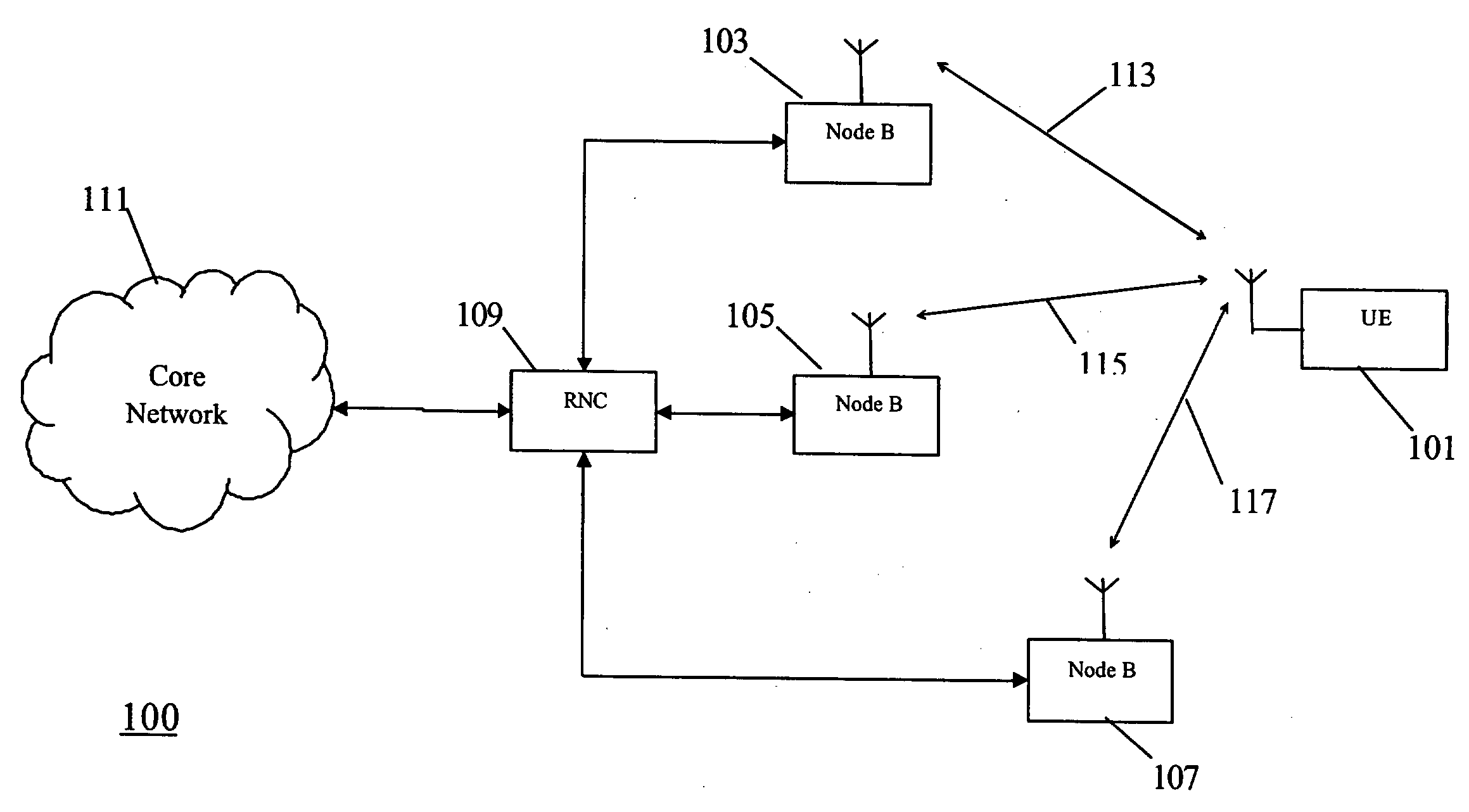
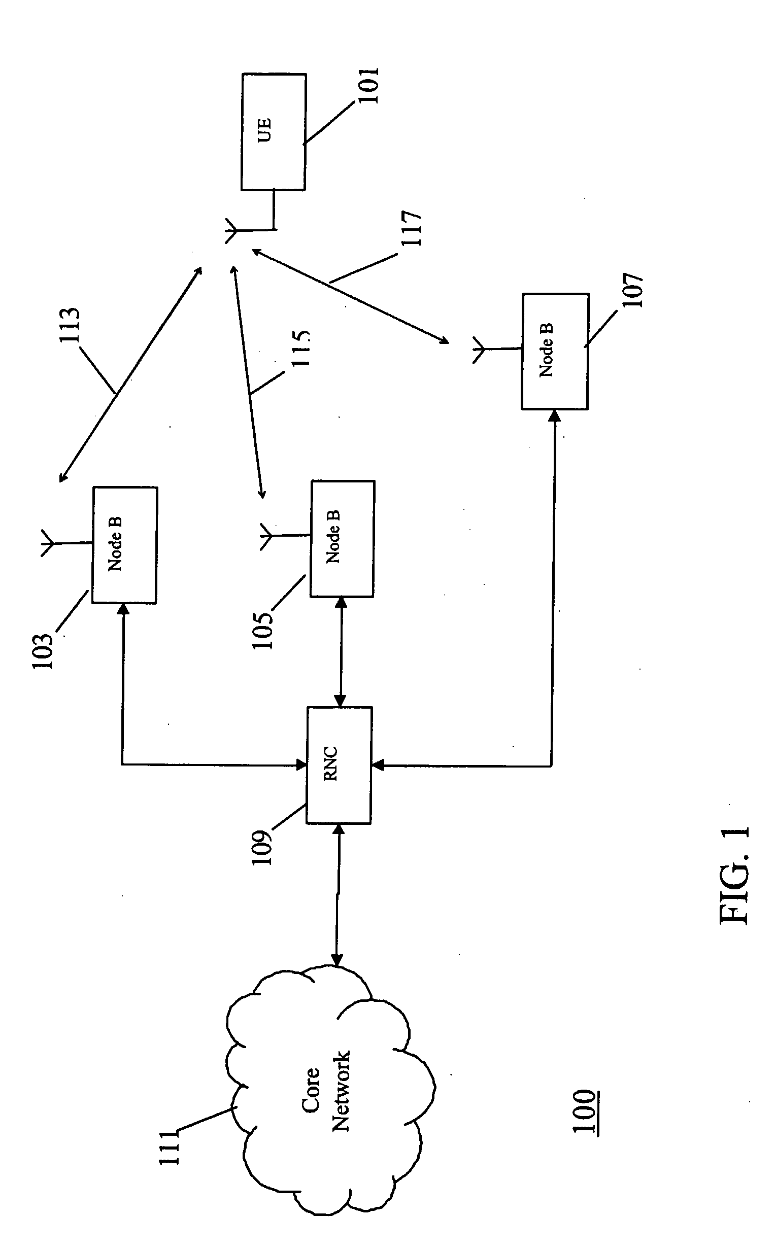
[0048]FIG. 1 is an illustration of a UMTS cellular communication system 100 incorporating some embodiments of the invention.

[0049]In the example of FIG. 1, a user equipment 101 is supported by three base stations (node Bs) 103, 105, 107. The three base stations 103-107 are coupled to a Radio Network Controller (RNC) 109 which is coupled to a core network 111 as is typical for UMTS cellular communication systems as will be well known to the person skilled in the art. In the example of FIG. 1, the user equipment 101 is in an overlap area between three different cells supported by the three different base station...


PUM


Abstract

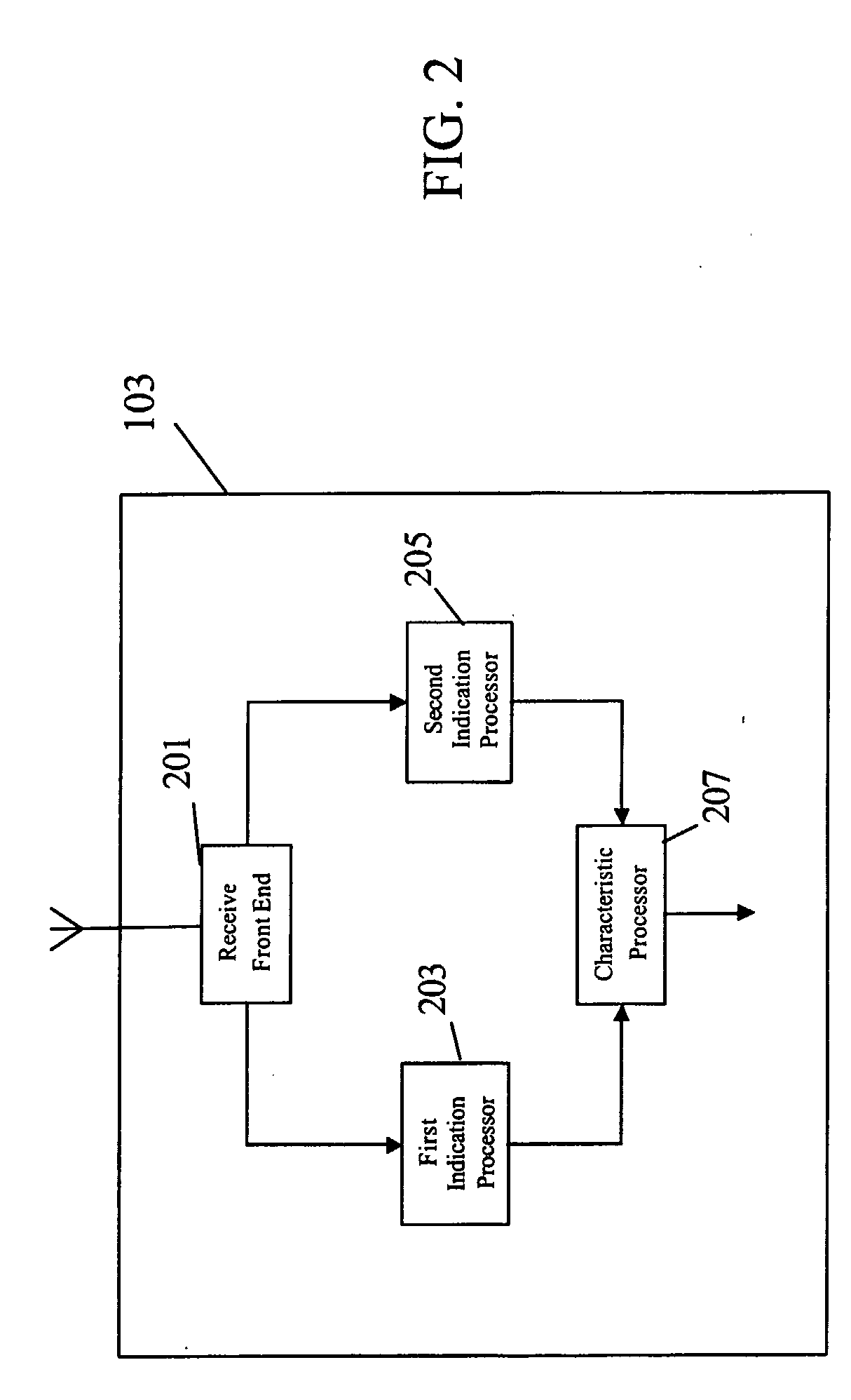
A cellular communication system supports both soft handover communication channels and non-soft handover communication channels from the same user equipment (101). A serving base station (103) comprises a receive front end (201) for receiving transmissions from the user equipment (101). A first indication processor (203) receives a first link quality indication associated with a first signal of a soft handover communication channel from the user equipment (101). A second indication processor 205 receives a second link quality indication associated with a second signal of a non-soft handover channel from the user equipment (101). A characteristic processor (207) then determines the radio link characteristic in response to the first and second link quality indications. For example a power control command for a soft handover signal and a channel quality indicator for a non-soft handover signal may be compared and a radio link quality may be determined in response to the comparison.

Description

FIELD OF THE INVENTION[0001]The invention relates to a method, apparatus and base station for determining a radio link characteristic and in particular, but not exclusively, for determining a radio link characteristic in a 3rd Generation cellular communication system.BACKGROUND OF THE INVENTION[0002]In a cellular communication system, a geographical region is divided into a number of cells served by base stations. The base stations are interconnected by a fixed network which can communicate data between the base stations. A mobile station is served via a radio communication link from the base station of the cell within which the mobile station is situated.[0003]A typical cellular communication system extends coverage over an entire country and comprises hundreds or even thousands of cells supporting thousands or even millions of mobile stations. Communication from a mobile station to a base station is known as the uplink, and communication from a base station to a mobile station is ...

Claims


Application Information

Patent Timeline
Patent Type & Authority Applications(United States)
IPC IPC(8): H04W36/00H04W36/30
CPCH04W36/30H04W36/0058H04W36/0055H04W36/302H04L5/0057H04W72/12
Inventor BARRETT, STEPHEN J.
Owner MOTOROLA INC
Learn More