Wireless device and system for monitoring physiologic parameters

a technology of physiologic parameters and wireless devices, applied in the field of wireless devices and systems for monitoring physiologic parameters, can solve the problems of inability to take advantage of silicon microfabrication technology, inability to deliver to patients with ease and minimal invasion, and inability to take advantage of recent advances in silicon microfabrication technology. , to achieve the effect of reducing the risk of infection for patients and physical injury or device damage, and reducing the risk of infection

Active Publication Date: 2009-07-16
UIM PRESSURE IMPLANT INC
View PDF3 Cites 122 Cited by
  • Summary
  • Abstract
  • Description
  • Claims
  • Application Information

AI Technical Summary

Benefits of technology

[0014]It is also an object of this invention to provide a system including an implantable device for monitoring blood pressure and other physiologic parameters that is delivered to the patient with ease and minimal invasion.
[0015]It is also an object of this invention to provide a method for delivering an implantable device for monitoring blood pressure and other physiologic parameters that is delivered to the patient with ease and minimal invasion.
[0016]The above objects are achieved by providing at least a self contained implantable sensing device consisting of a sensor, an

Problems solved by technology

Wireless sensors in particular are highly desirable for biologic applications because the transcutaneous passage of wires (or other communication “tethers”) risks both infection to the patient and physical injury or device damage if the communication link experiences excessive pulling force.
The '276, '110, and '558 patents, although feasible, do not take advantage of recent advances in silicon (or similar) microfabrication technologies.
This device must be “assembled” around the vessel being monitored such that it fully encompasses the vessel, which may not be feasible in many cases.
Such a device would be advantageous for monitoring elevated eye pressures (as is usually the case for glaucoma patients); however, the requirement that the eye's cryst

Method used


Image

  • Wireless device and system for monitoring physiologic parameters
  • Wireless device and system for monitoring physiologic parameters
  • Wireless device and system for monitoring physiologic parameters

Examples


Embodiment Construction

[0022]The following description of preferred embodiments and methods provides examples of the present invention. The embodiments discussed herein are merely exemplary in nature, and are not intended to limit the scope of the invention in any manner. Rather, the description of these preferred embodiments and methods serves to enable a person of ordinary skill in the relevant art to make, use and perform the present invention.

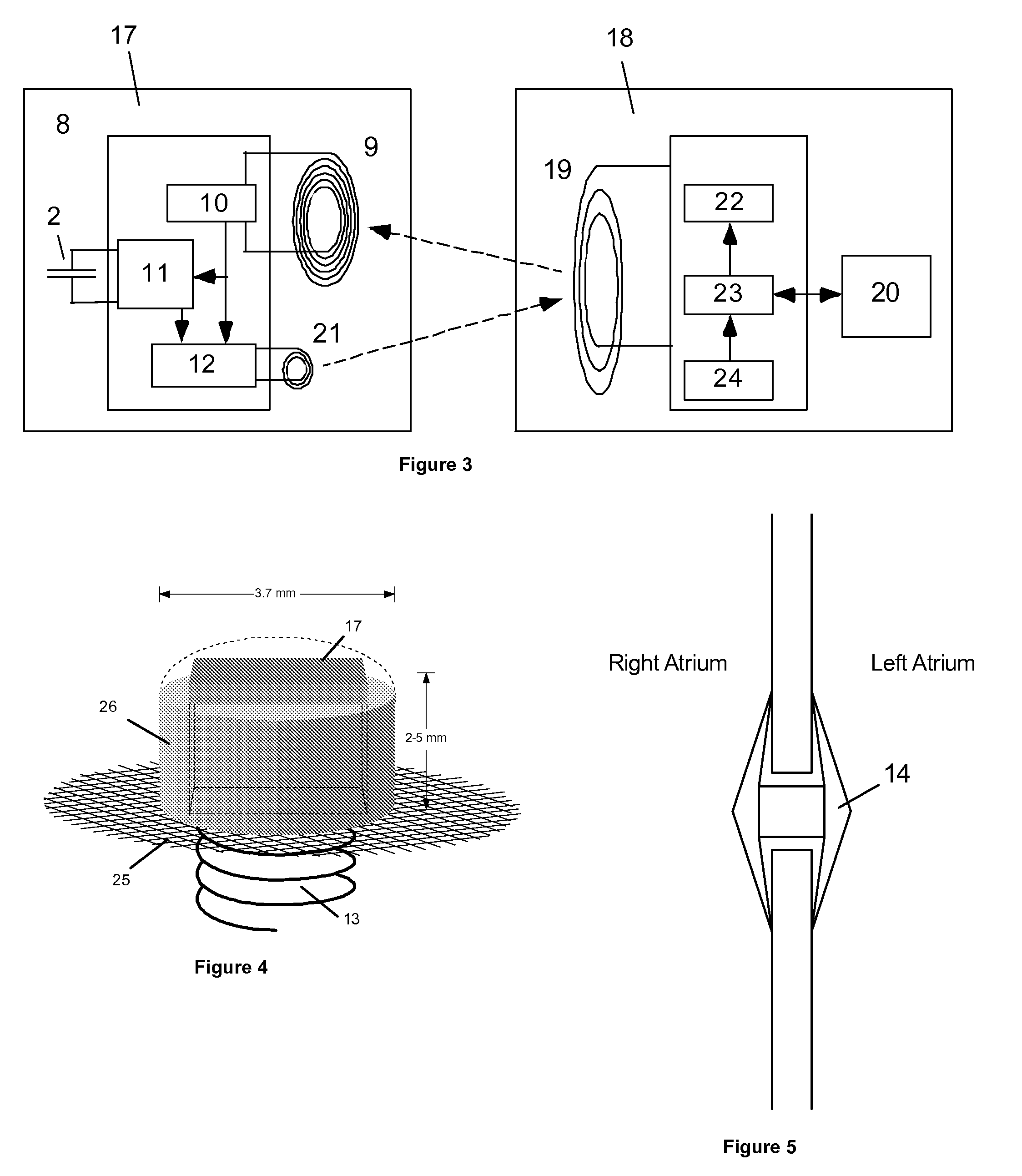
[0023]The preferred communication scheme for the present invention, shown in FIG. 3, is based on magnetic telemetry. Without an external reader present, the implant device lays passive and without any internal means to power itself. When a pressure reading is desired, the reader device is brought into a suitable range to the implant. The reader then creates an RF (Radio Frequency) magnetic field large enough to induce sufficient voltage across the implant coil. When such a sufficient voltage exists across the implant coil, the implant circuit may rectify the alte...


PUM


Abstract

A system for monitoring blood pressure and other physiologic parameters is provided. The system is designed such that it can be delivered to the patient with ease and minimal invasion. The system contains at least one self contained implantable sensing device consisting of a sensor, an electrical circuit for signal conditioning and magnetic telemetry, a biocompatible outer surface and seal, an anchoring method, and an external readout device. The implant is small in size so that it may be delivered to the desired location and implanted using a catheter, although direct surgical implantation is also possible. The circuit, sensor, and antenna for telemetry are packaged together and sealed hermetically to the biologic environment. The larger readout unit remains outside the body but proximal to the implant for minimizing communication distance.

Description

REFERENCE TO PREVIOUS APPLICATIONS[0001]This application is a Division of co-pending U.S. patent application Ser. No. 10 / 677,674 filed Oct. 2, 2003.FIELD OF THE INVENTION[0002]This invention relates generally to medical devices monitoring blood pressure and other physiologic parameters.BACKGROUND OF THE INVENTION[0003]A number of different physiologic parameters are strong candidates for continuous monitoring, such as blood pressure or flow, cardiovascular pressure, intracranial pressure, intraocular pressure, glucose levels, etc. Wireless sensors in particular are highly desirable for biologic applications because the transcutaneous passage of wires (or other communication “tethers”) risks both infection to the patient and physical injury or device damage if the communication link experiences excessive pulling force.[0004]A large number of proposed schemes for non-medical wireless communication rely on magnetic coupling between an electrical coil in an implanted device and a separa...

Claims


Application Information

Patent Timeline
IPC IPC(8): A61B5/00
CPCA61B5/0031A61B2560/0219A61B5/6882A61B5/0215A61N1/37223
Inventor NAJAFI, NADERMASSOUD-ANSARI, SONBOLRICH, COLLIN ANDERSON
Owner UIM PRESSURE IMPLANT INC
Why Eureka
Try Eureka