Fault location device, communication device, and fault location method

Active Publication Date: 2009-07-16
TOYOTA JIDOSHA KK
View PDF5 Cites 53 Cited by
  • Summary
  • Abstract
  • Description
  • Claims
  • Application Information

AI Technical Summary

Benefits of technology

[0029]According to the above described fault location device, communication device and fault location method, it is

Problems solved by technology

In the above first aspect, the communication error may include a transmission error and a reception error.
When there is a communication device whose transmission error counter accumulated val

Method used


Image

  • Fault location device, communication device, and fault location method
  • Fault location device, communication device, and fault location method
  • Fault location device, communication device, and fault location method

Examples


Example

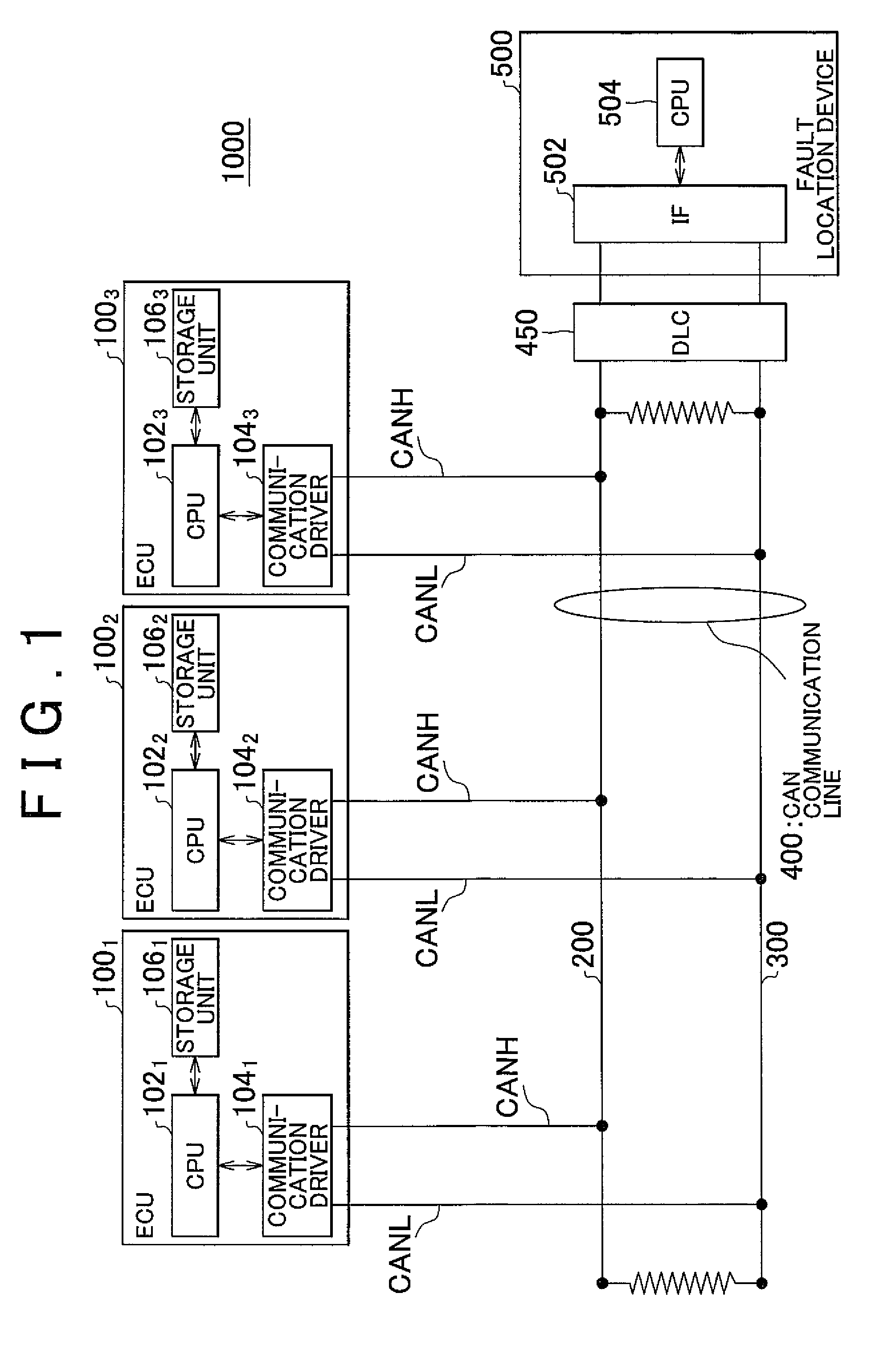
[0040]A CAN communication system according to a first embodiment of the invention will be described with reference to FIG. 1. FIG. 1 also shows a DLC 450 and a fault location device 500. The DLC 450 and the fault location device 500 are connected to the CAN communication system when a fault point is detected.

[0041]The CAN communication system 1000 according to the present embodiment, for example, includes a plurality of communication devices that carry out communications in accordance with the communication protocol of an in-vehicle LAN. For example, the communication protocol of the in-vehicle LAN may employ a controller area network (CAN). The communication devices are respectively formed of a plurality of electronic control units (ECUs) that control various portions of a vehicle.

[0042]In the CAN, as described above, a communication line (communication bus) uses a two-wire CAN communication line 400 formed of a CANH 200 and a CANL 300, and a terminator is connected at each end of ...

Example

[0077]A CAN communication system according to a second embodiment of the invention will be described.

[0078]The configuration of the CAN communication system according to the second embodiment is similar to the configuration described with reference to FIG. 1.

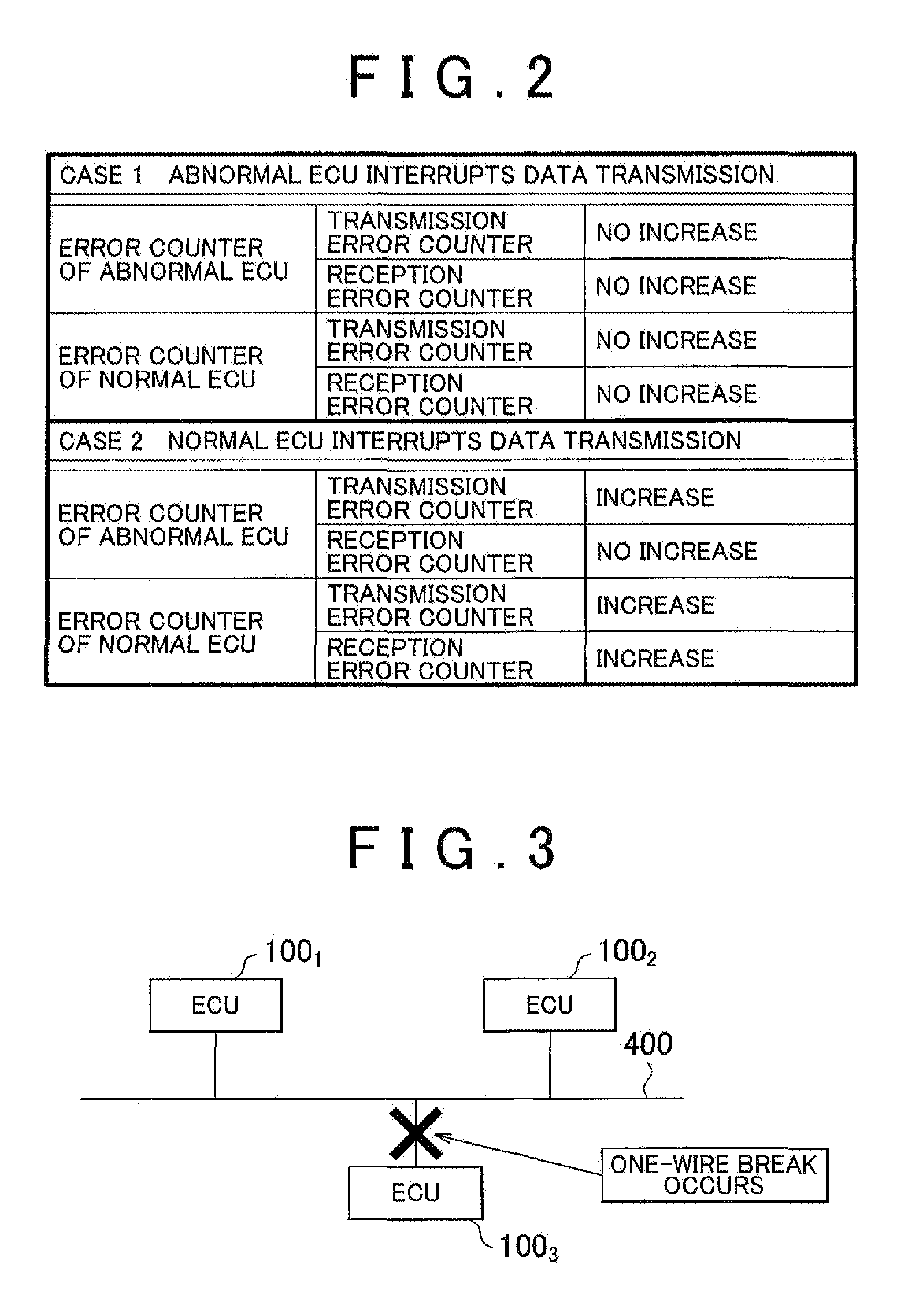
[0079]In the fault location device 500 according to the second embodiment, on the basis of the transmission and reception error counter accumulated values recorded in all the ECUs, while an ECU is in a bus off state, when there is an ECU whose transmission error counter accumulated value increases and whose reception error counter accumulated value does not increase, the CPU 504 estimates that a communication line to that ECU is broken.

[0080]In addition, on the basis of the transmission and reception error counter accumulated values recorded in all the ECUs, while an ECU is in a bus off state, when there is an ECU whose transmission error counter accumulated value does not increase and whose reception error counter accumulated v...

Example

[0098]A CAN communication system according to a third embodiment of the invention will be described.

[0099]The configuration of the CAN communication system according to the third embodiment differs from the above described embodiments in that, as shown in FIG. 8, the functions of the fault location device that identifies a fault point are incorporated into the ECU.

[0100]In the present embodiment, the case in which the functions of the fault location device are incorporated into the ECU 1001 will be described. This ECU may be configured as a master ECU.

[0101]The CPU 1022 and CPU 1023 of the other ECUs 1002 and 1003, when communications returns to a normal state, transmit the transmission and reception error counter accumulated values and the error detection time to the ECU 1001 through the CAN communication line 400. The transmission timing may be a regular transmission timing of each ECU or the transmission may be performed so that the ECU 1001 inquires the transmission of each ECU ...


PUM


Abstract

A fault location device detects a communication device connected to a broken communication line from among communication devices that carry out communications between each other through a two-wire communication line. The communication device, when detecting a communication error, stores communication error time and a communication error counter accumulated value indicating accumulated counts of the communication error, changes into a bus off state on the basis of the communication error counter accumulated value, and, after a predetermined period of time, returns from the bus off state. The fault location device includes an acquisition unit that acquires the communication error time and communication error counter accumulated value, stored in each communication device; and a detection unit that detects a communication device connected to a broken communication line on the basis of variations in the communication error counter accumulated values while any one of the communication devices is in a bus off state.

Description

INCORPORATION BY REFERENCE[0001]The disclosure of Japanese Patent Application No. 2008-003101 filed on Jan. 10, 2008 including the specification, drawings and abstract is incorporated herein by reference in its entirety.BACKGROUND OF THE INVENTION[0002]1. Field of the Invention[0003]The invention relates to a controller area network (CAN) communication system and method by which communications are carried out among a plurality of communication devices connected through a CAN bus and, more particularly, to a fault location device, communication device, and fault location method that are able to identify a fault point due to a one-wire break.[0004]2. Description of the Related Art[0005]A known CAN communication system carries out data communications among a plurality of communication devices. The plurality of communication devices are connected with one another through a CAN bus, and each have a CAN controller unit. The CAN communication protocol allows bidirectional serial communicat...

Claims


Application Information

Patent Timeline
IPC IPC(8): G06F11/00
CPCH04L43/0823H04L2012/40273H04L2012/40215
Inventor ANDO, HIROYA
Owner TOYOTA JIDOSHA KK
Why Eureka
Try Eureka