
Installation head actuator for electronic parts and installation device for electronic parts

a technology of electronic parts and actuators, which is applied in metal-working equipment, metal-working equipment, manufacturing tools, etc., can solve the problems of increasing throughput, limiting, etc., and achieve the effect of preventing the production of printed circuit boards and high installation accuracy of electronic parts

Inactive Publication Date: 2009-07-23
HITACHI HIGH TECH INSTR CO LTD
View PDF16 Cites 8 Cited by
  • Summary
  • Abstract
  • Description
  • Claims
  • Application Information

AI Technical Summary

Benefits of technology

[0007]By taking the problems mentioned above into the consideration thereof, according to the present invention, an object thereof is to provide an installation device for electronic parts having a high reliability, while increasing the throughput by maximizing the parallel operation of the motor, etc., and reducing the contacts and the interferences generating during that parallel operation.

Problems solved by technology

However, with the technology described in the Patent Document 1, because a motor is applied, also to select the suction nozzle, due to the operational limit and the mechanical restriction, etc., of the motor, which can be installed in the installation head actuator, there is a limitation, in particular, for increasing the throughput thereof.
Also, because of an increase of operating speed of the motor, vibrations come to be large, which are caused due to contact and / or interference generating during parallel operation thereof, and generating slip-out of shifting of a chip, therefore it is the greatest reason of generating the mal-circuit in the printed circuit boards.

Method used


Image

  • Installation head actuator for electronic parts and installation device for electronic parts
  • Installation head actuator for electronic parts and installation device for electronic parts
  • Installation head actuator for electronic parts and installation device for electronic parts

Examples


Embodiment Construction

[0028]Hereinafter, embodiments according to the present invention will be fully explained by referring to the attached drawings.

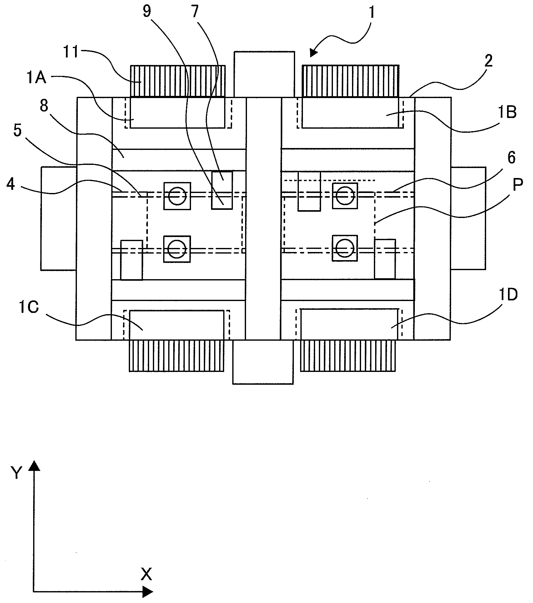
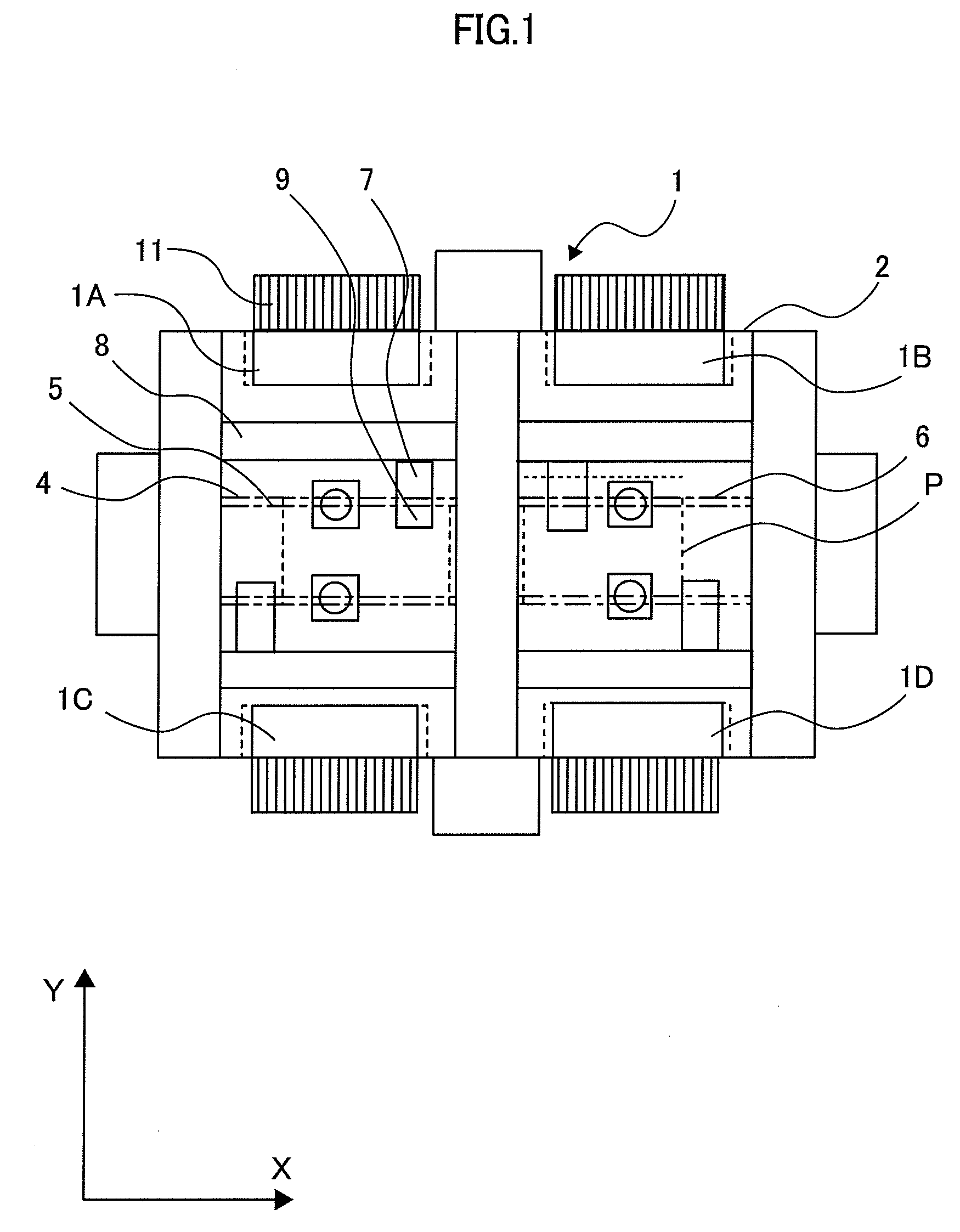
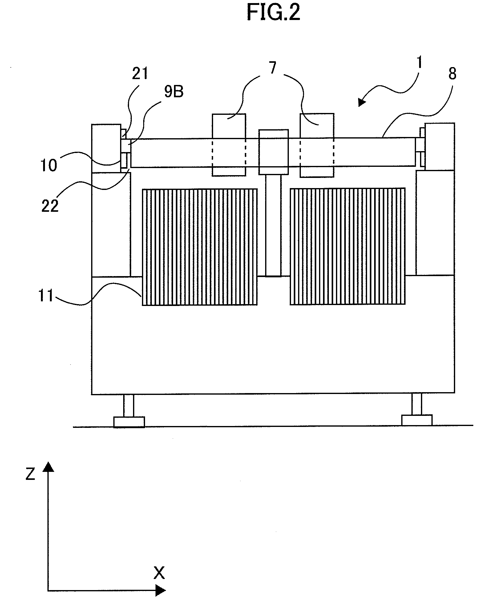
[0029]FIG. 1 attached herewith is a front view of an installation device 1 for electronic parts (hereinafter, an electronic parts installation device), according to an embodiment of the present invention. FIG. 2 is a front view of a main body of a lower portion of the electronic parts installation device 1. Upon feeder basses 1A, 1B, 1C and 1D on a base 2 of the electronic parts installation device 1 are fixed plural numbers of parts supply units 11 in parallel with, respectively, each for supplying various kinds of electronic parts “D” to a part takeout position (i.e., a part suction position), one by one, under an immovable condition, but in a detachable manner. Between groups of the units facing to each other is provided a supply conveyer 4, a positioning unit 5 and a discharge conveyer 6. The supply conveyer 4 transfers a printed circuit board “P”, whic...


PUM

PropertyMeasurementUnit
Magnetic forceaaaaaaaaaa

Abstract

In an electronic parts installation device, increasing throughput by brining parallel operation of motors, etc., to the maximum, and having high reliability by reducing contacts and / or interferences generating the parallel operations, an electronic parts installation head actuator 9, comprises a plural number of suction nozzles 115, each for sucking an electronic part to install it on a printed circuit board, a nozzle selector member 301 for selecting a predetermined suction nozzle from the plural number of suction nozzles 115, and an elevating device 101 for elevating the plural number of suction nozzles 115, wherein the nozzle selector member 301 has a permanent magnet for attracting the suction nozzle 115, which is biased in one direction by a spring 112, to the direction opposite to that one direction, and an excitation coil for neutralizing a magnetic force of the permanent magnet by applying current therein.

Description

BACKGROUND OF THE INVENTION[0001]The present invention relates to an installation head actuator for electronic parts, for taking out electronic parts by a suction nozzle, so as to install them on a printed circuit board, and also an installation device for electronic parts with using the same therein.[0002]Conventionally, when installing the electronic parts on the printed circuit board, an installation device is applied, i.e., for picking up the electronic parts from a parts supply unit, by the suction nozzle, and thereby installing them on the printed circuit board.[0003]For example, in the installation device for electronic parts described in the following Patent Document 1, an installation head actuator equipped with plural numbers of suction nozzles, after sucking the electronic parts, moves to a position above the printed circuit board, and installs them at predetermined positions. In case when sucking the electronic part onto one (1) nozzle from a group of nozzles (hereinafte...

Claims


Application Information

Patent Timeline
IPC IPC(8): B23P19/00
CPCH05K13/0408Y10T29/53174H05K13/0452H05K13/0413H05K13/041B65G47/91H05K3/30H05K13/04
Inventor TAKAHIRA, ISAOKASHITANI, HISAYOSHIURATA, NAOKI
Owner HITACHI HIGH TECH INSTR CO LTD
Learn More