

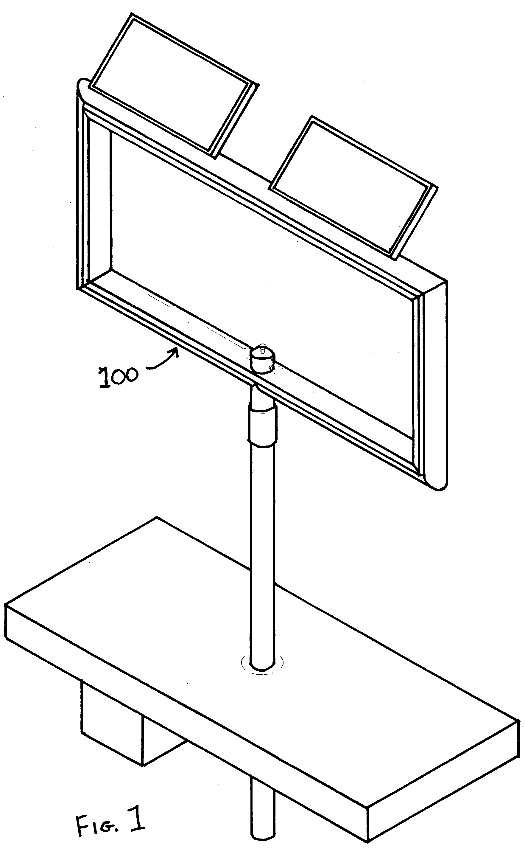
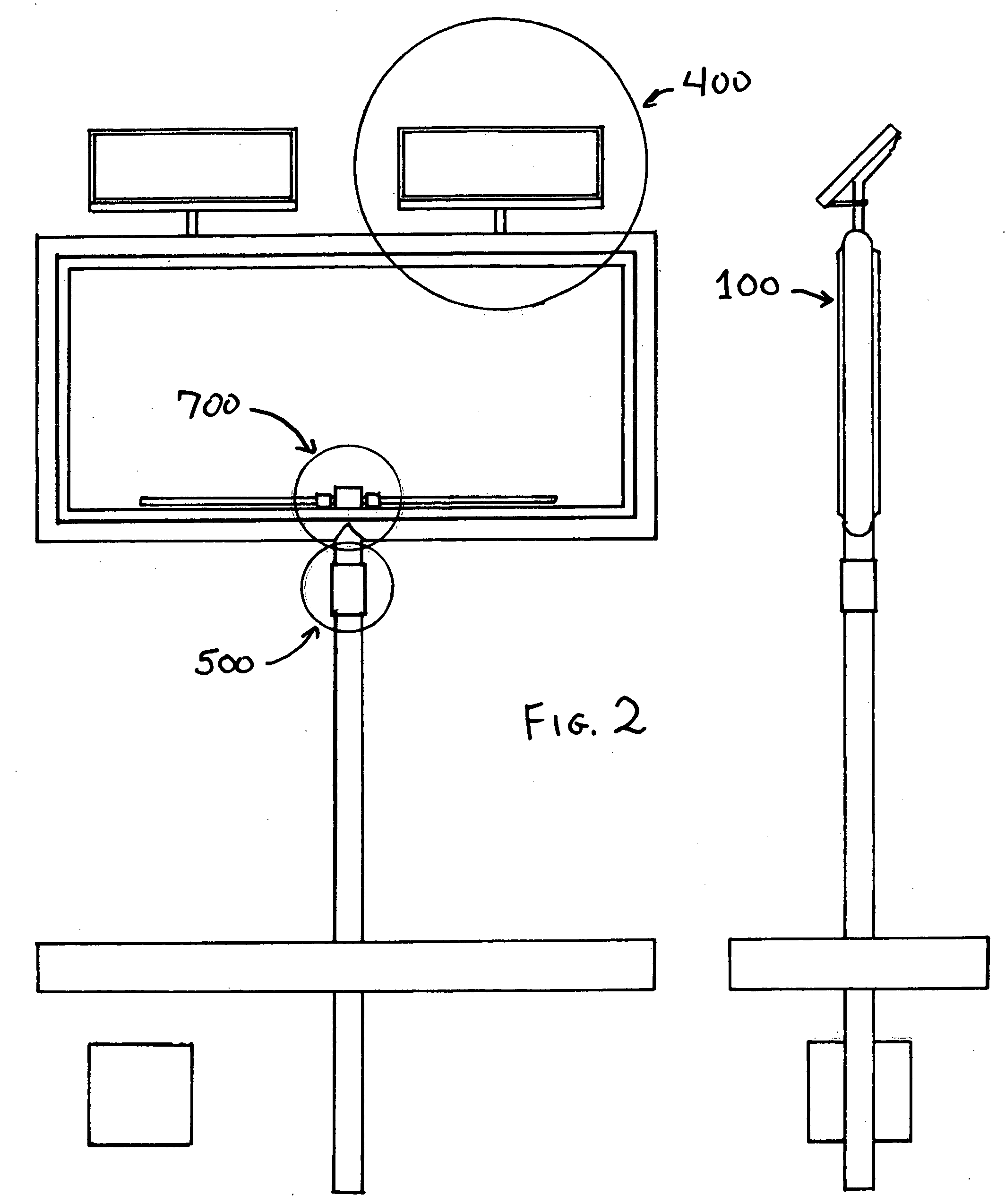
Solar powered internally illuminated billboard
a technology of solar energy and billboards, applied in secondary cells, process and machine control, instruments, etc., can solve the problems of inability laborious and time-consuming, and no previous effort has been made to provide internal illuminated billboard type signag
- Summary
- Abstract
- Description
- Claims
- Application Information
AI Technical Summary
Benefits of technology
Problems solved by technology
Method used
Image


Examples
Embodiment Construction
[0030]It is an object of the present invention to provide a practical sign frame for solar powered internally illuminated outdoor signage and billboards.
[0031]It is another object of the present invention to provide sign frame with an integrated, simple means for attaching solar photovoltaic modules.
[0032]It is yet another object of the present invention to provide a sign frame that maximizes the utilization of limited illumination means.
[0033]The present invention builds on the approaches described in the foregoing paragraphs, and improves significantly the utilization of solar or other scarce and valuable energy resources through a new approach to managing load. In one embodiment of the invention run time for powering the load is calculated by means of an algorithm that combines user preferences, existing system capacity, and future solar recharging resources.
[0034]The sign frame element of the present invention comprises a cost effective means for the utilization of solar power i...
PUM
 Abstract
Description
Claims
Application Information