Split-Series Sequential Turbocharged Engine

a turbocharged engine and split-series technology, applied in combustion engines, machines/engines, engine controllers, etc., to achieve the effect of efficient operation

Inactive Publication Date: 2009-07-23
FORD GLOBAL TECH LLC
View PDF20 Cites 22 Cited by
  • Summary
  • Abstract
  • Description
  • Claims
  • Application Information

AI Technical Summary

Benefits of technology

[0015]As seen in FIGS. 3 and 4, cylinder banks 2, 4 together form an engine block 70 having a V configuration and which defines a generally V-shaped valley 60 between the cylinder banks, as is well known in the art. High pressure turbocharger 18 is positioned as deep as possible in the bottom of valley 60 so that it projects very little, if any, above the upper ends of cylinder banks 2, 4. Also in the depicted embodiment of the invention, low pressure turbochargers 24, 26 are positioned closely adjacent to the outer sides of respective cylinder banks 2, 4. This configuration of the turbocharger system is very space-efficient, resulting in a compact engine/turbo unit.
[0016]The engine/turbocharger configuration depicted in FIGS. 1 and 2 allows t

Problems solved by technology

In some automotive applications, one of the engineering challenges is making the system fit into the available packaging space wi

Method used


Image

  • Split-Series Sequential Turbocharged Engine
  • Split-Series Sequential Turbocharged Engine
  • Split-Series Sequential Turbocharged Engine

Examples


Embodiment Construction

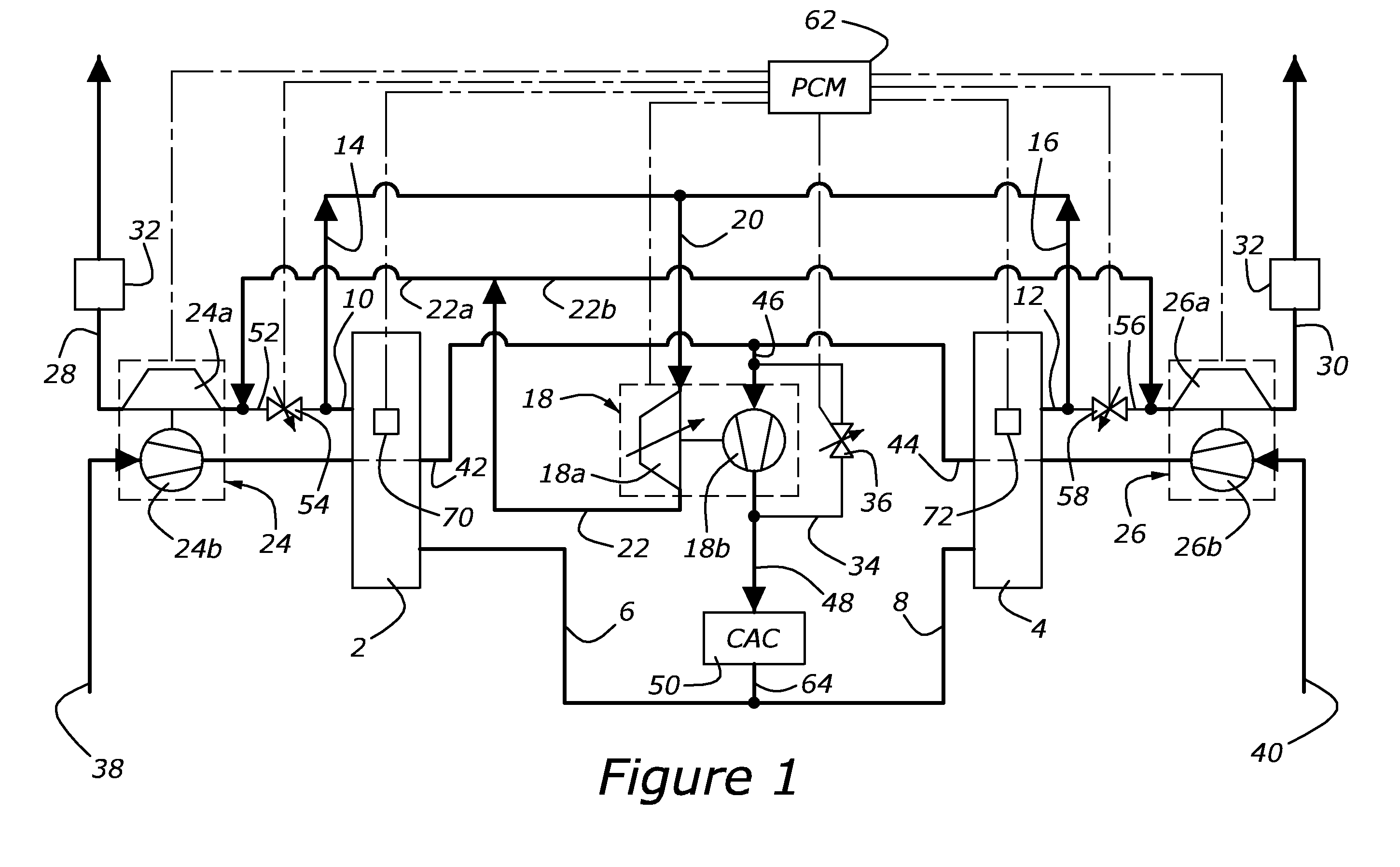
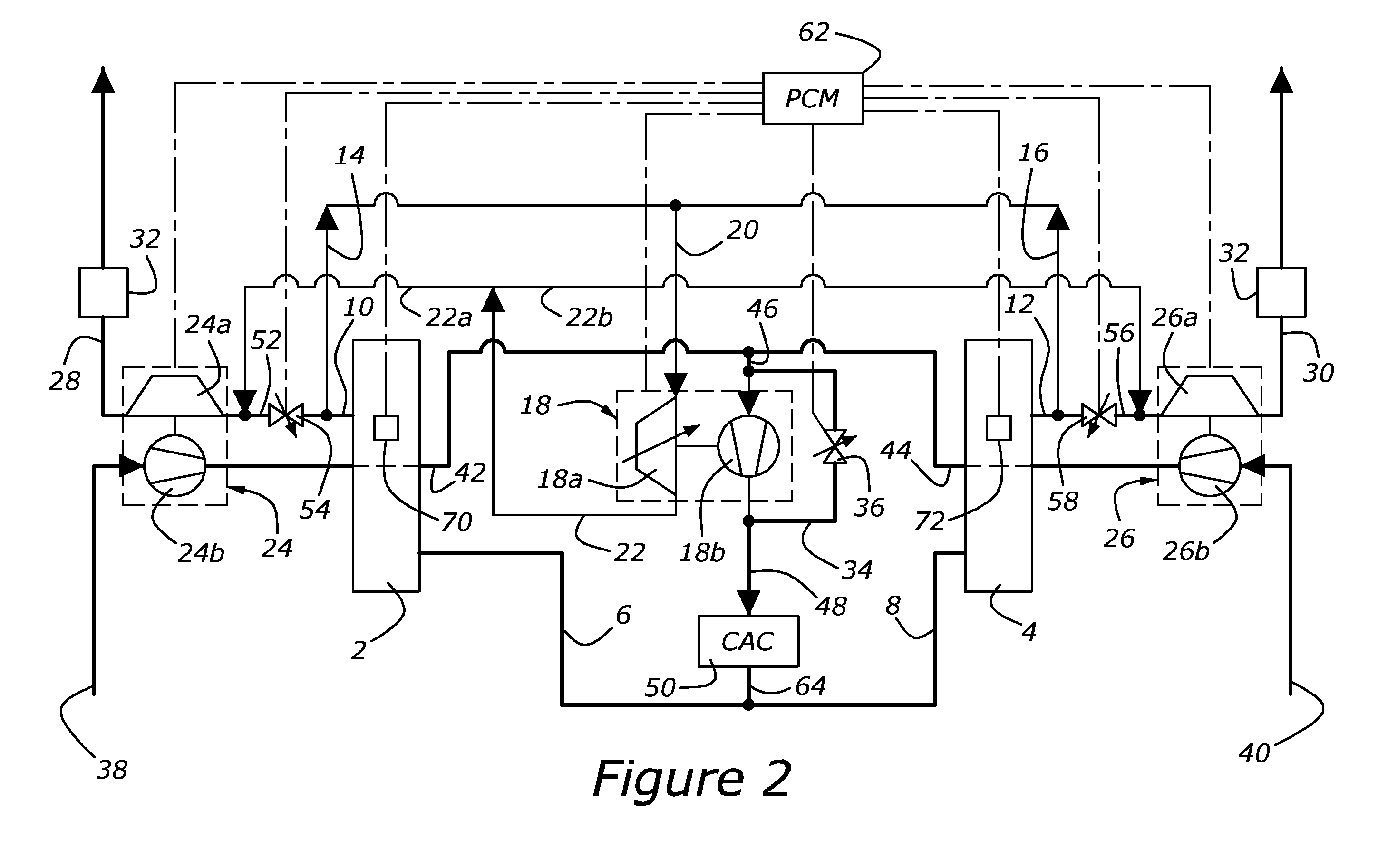
[0008]FIGS. 1 and 2 show in schematic form an engine and turbocharger system according to an embodiment of the present invention. The engine comprises left and right cylinder banks 2, 4 each of which may have any number of cylinders. Pre-combustion air is supplied to cylinder banks through intake manifolds 6, 8 respectively and post-combustion exhaust is expelled from cylinder banks through exhaust manifolds 10, 12 respectively. High pressure turbine feed ducts 14, 16 extend from exhaust manifolds 10, 12 to a high pressure turbocharger 18. High pressure turbocharger 18 comprises a turbine portion 18a and a compressor portion 18b, as is well known in the art. The two high pressure turbine feed ducts 14, 16 are shown to join together into a single turbine intake duct 20 at a point prior to feeding into high pressure turbocharger 18, however the two high pressure turbine feed ducts may feed separately into high pressure turbocharger 18. High pressure turbine feed ducts 14, 16 and turbi...


PUM


Abstract

For an internal combustion engine having two cylinder banks forming a V-shaped cylinder block, a turbocharger system including a high pressure turbocharger disposed in a valley between the cylinder banks, a first low-pressure turbocharger disposed adjacent an outer side of one of the cylinder banks, and a second low-pressure turbocharger disposed adjacent an outer side of the second cylinder bank. Intake and exhaust ducts connect the components of the engine and turbocharger system to and electronically controlled valves associated with the ducts permit the system to operate either in a split series mode or a low-pressure-only mode.

Description

FIELD OF THE INVENTION[0001]The invention relates to turbocharged internal combustion engines and specifically to such an engine wherein the turbocharger system includes a single high-pressure stage in series with two low-pressure stages, the low-pressure stages arranged in parallel with one another.BACKGROUND[0002]The benefits of applying turbocharging to an internal combustion engine are well known. These benefits include improved maximum unit power per unit engine displacement, improved volumetric efficiency, and reduced engine emissions. It is known to utilize multiple stages within a turbocharging system. In some automotive applications, one of the engineering challenges is making the system fit into the available packaging space within the vehicle engine compartment while minimizing the length of the ducting between the engine and the turbocharger components. A variety of different physical layouts of the turbocharger components have been utilized in order to meet these design...

Claims


Application Information

Patent Timeline
IPC IPC(8): F02B29/04F02B33/34F02D23/00
CPCF02B37/007F02B37/013F02B37/16F02B37/18F02B67/10F02B75/22Y02T10/144F02B37/001F02B37/004F02B37/24Y02T10/12
Inventor TROMBETTA, CHRISTOPHER BERNARDBRIGGS, MICHAEL LEONSCHORN, NORBERT ANDREASSTYLES, DANIEL JOSEPH
Owner FORD GLOBAL TECH LLC
Why Eureka
Try Eureka