Grease Sampling Kit, Grease Sampling Devices Made from the Kit, and Related Methods

Active Publication Date: 2009-07-23
WURZBACH RICHARD N
View PDF13 Cites 9 Cited by
  • Summary
  • Abstract
  • Description
  • Claims
  • Application Information

AI Technical Summary

Benefits of technology

[0008]The present invention is a kit of component parts for forming a set of grease sampling devices for obtaining representative grease samples from bearings. The component parts enable a grease sampling device to be easily assembled that is suited for the particular configuration of the bearing from which t

Problems solved by technology

Discharging excess grease relieves the pressure within the housing, preventing a buildup of back pressure when the housing is filled that might

Method used


Image

  • Grease Sampling Kit, Grease Sampling Devices Made from the Kit, and Related Methods
  • Grease Sampling Kit, Grease Sampling Devices Made from the Kit, and Related Methods
  • Grease Sampling Kit, Grease Sampling Devices Made from the Kit, and Related Methods

Examples


first embodiment

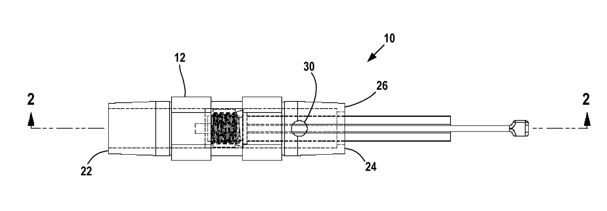
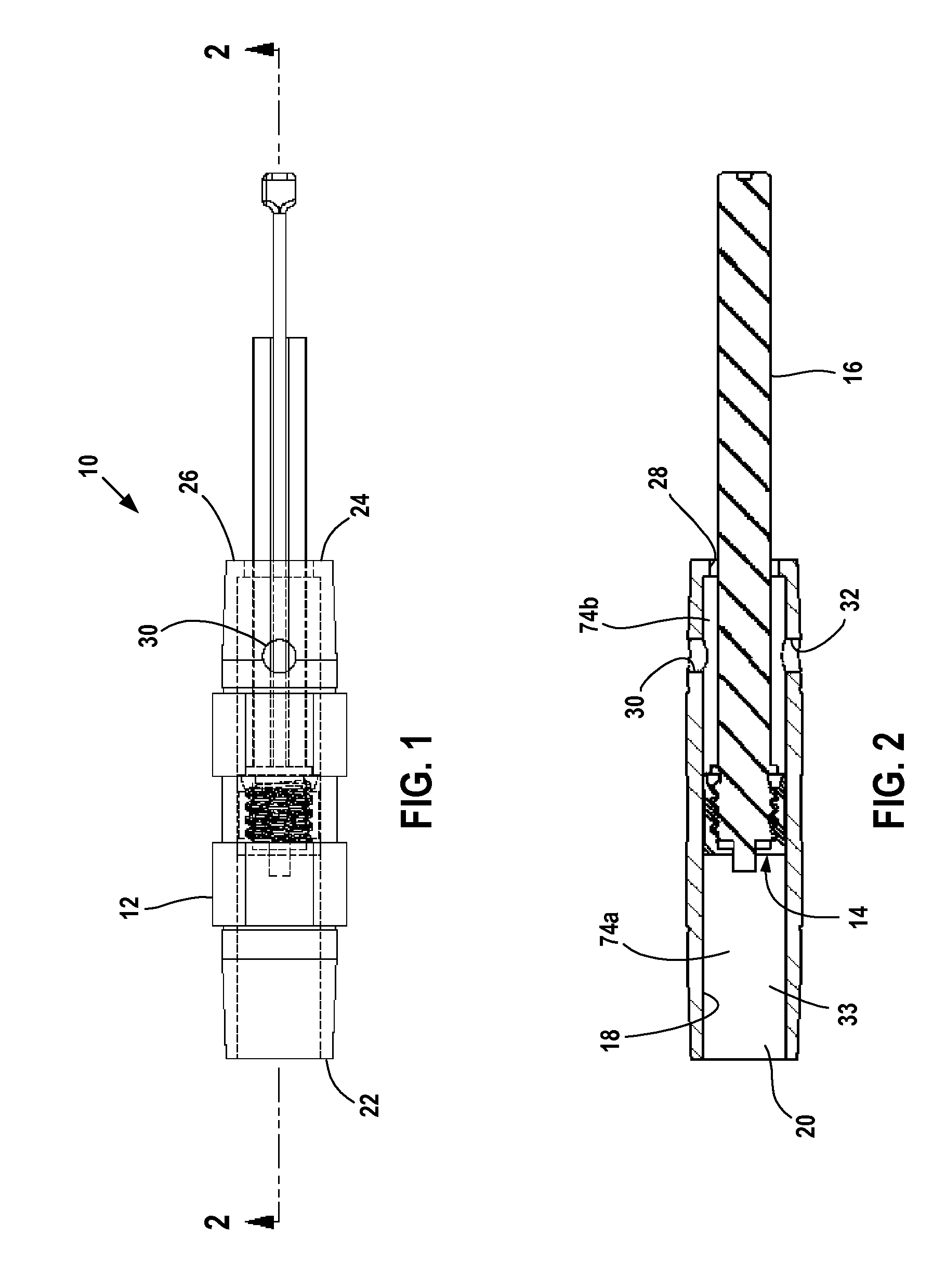
[0034]FIGS. 1 and 2 illustrate a first embodiment grease sampling device 10 formed from the kit's component parts. Grease sampling device 10 is intended for obtaining a grease sample from a source of pressurized grease as will be explained in greater detail later.

[0035]Grease sampling device 10 includes a tubular housing or barrel 12 and a piston 14 slideably mounted in the barrel. A piston rod 16 extends from one side of the piston 14 and out of the housing 12.

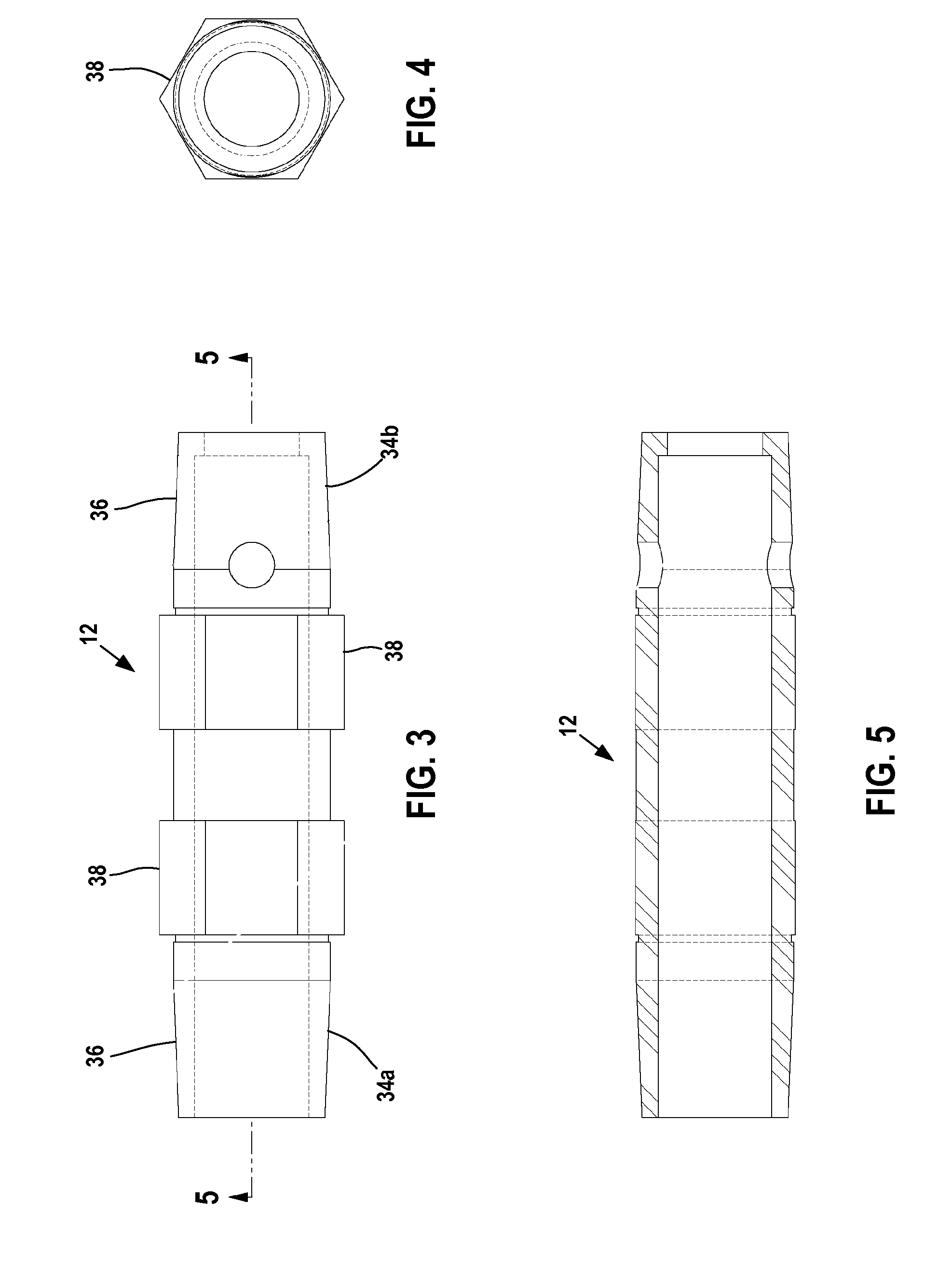
[0036]Housing 12 is preferably formed from a transparent plastic, and has an annular body or wall 18 that surrounds the housing bore 20. Housing 12 extends axially from an open housing end 22 to a partially closed housing end 24. End wall 26 closes housing end 24 and includes a coaxial opening 28 that receives the piston rod 16. A pair of through openings or vent holes 30, 32 extends through the housing body 18 and communicates the interior 33 of the housing 12 with the exterior. Openings 30, 32 are axially spaced away from t...

second embodiment

[0056]FIG. 13 illustrates a second embodiment grease sampling device 110 formed from the kit's component parts. Grease sampling device 110 obtains a grease sample from adjacent a rigid bearing surface as will be explained in greater detail later.

[0057]Grease sampling device 110 includes a tubular housing or barrel 112 and a piston 114 slideably mounted in the housing 112. A piston rod 116 extends from one side of the piston 114 and out of the housing 112. An elongate push rod 118 extends from the other side of the piston 114.

[0058]Housing 112 is identical to the housing 12 and so will not be described in further detail.

[0059]Piston 114, piston rod 116, and push rod 118 are formed by threading a tubular piston body 120 onto a piston shaft 122. Piston body 120 is identical to the piston body 40 and so also will not be described in further detail.

[0060]Piston shaft 122 has a threaded attachment portion 124 identical to the attachment portion 56 and a piston rod 116 identical to piston ...


PUM


Abstract

A kit of component parts for forming at least first and second grease sampling devices includes a number of housings, piston bodies, and piston shafts. A first grease sampling device has a piston movable in the barrel and vent holes that resists the buildup of back pressure when the device is filled with a grease sample. A second grease sampling device includes a push rod extending from the piston that enables a representative grease sample to be obtained from a bearing, gear or other lubricated part that is not easily accessible.

Description

[0001]This application claims priority to my provisional patent application No. 61 / 022,404 filed Jan. 21, 2008.FIELD OF THE INVENTION[0002]The invention relates to devices for obtaining samples of lubricating grease from machine bearings, gears or other grease-lubricated components, a grease sampling kit having components for making such grease sampling devices, and related methods of obtaining grease samples from machine lubricated surfaces.BACKGROUND OF THE INVENTION[0003]It is estimated that 90% of all machine bearings are lubricated by grease. While oil analysis is a widespread tool for monitoring bearing and lubricated component health of important oil lubricated equipment, grease analysis is not generally adopted in a similar manner for important grease lubricated machines. Analyzing a sample of grease taken from a grease-lubricated bearing sometimes is performed to pinpoint the cause of bearing problems in failure analysis. However, the ability to adopt regular and routine gr...

Claims


Application Information

Patent Timeline
IPC IPC(8): G01N1/14
CPCF16N29/00G01N2001/1427G01N1/14
Inventor WURZBACH, RICHARD N.
Owner WURZBACH RICHARD N
Why Eureka
Try Eureka