Utility vehicle

a utility vehicle and design technology, applied in the direction of roofs, movable seats, transportation and packaging, etc., can solve the problems of reducing the ease of ingress/exit for passengers, affecting the feeling of spaciousness for passengers, etc., to achieve more compact cabin, more compact, and more compact

Active Publication Date: 2009-07-23
YAMAHA MOTOR CO LTD +1
View PDF7 Cites 29 Cited by
  • Summary
  • Abstract
  • Description
  • Claims
  • Application Information

AI Technical Summary

Benefits of technology

[0009]Given the vehicle as set forth in the present invention, the lower portion of the third roof support that is positioned lower than at least the seating surface of the seat cushion portion of the rear seat is angled so as to be further toward the back the higher up, enabling the rear wheels to be positioned further forward, making it possible to make the vehicle more compact while

Problems solved by technology

While one may consider shortening the front/back length of the rear floor in order to achieve a more compact vehicle, doing so

Method used


Image

  • Utility vehicle
  • Utility vehicle
  • Utility vehicle

Examples


Embodiment Construction

[0026]Exemplary embodiments of the present invention will be explained in further detail below with reference to the accompanying figures.

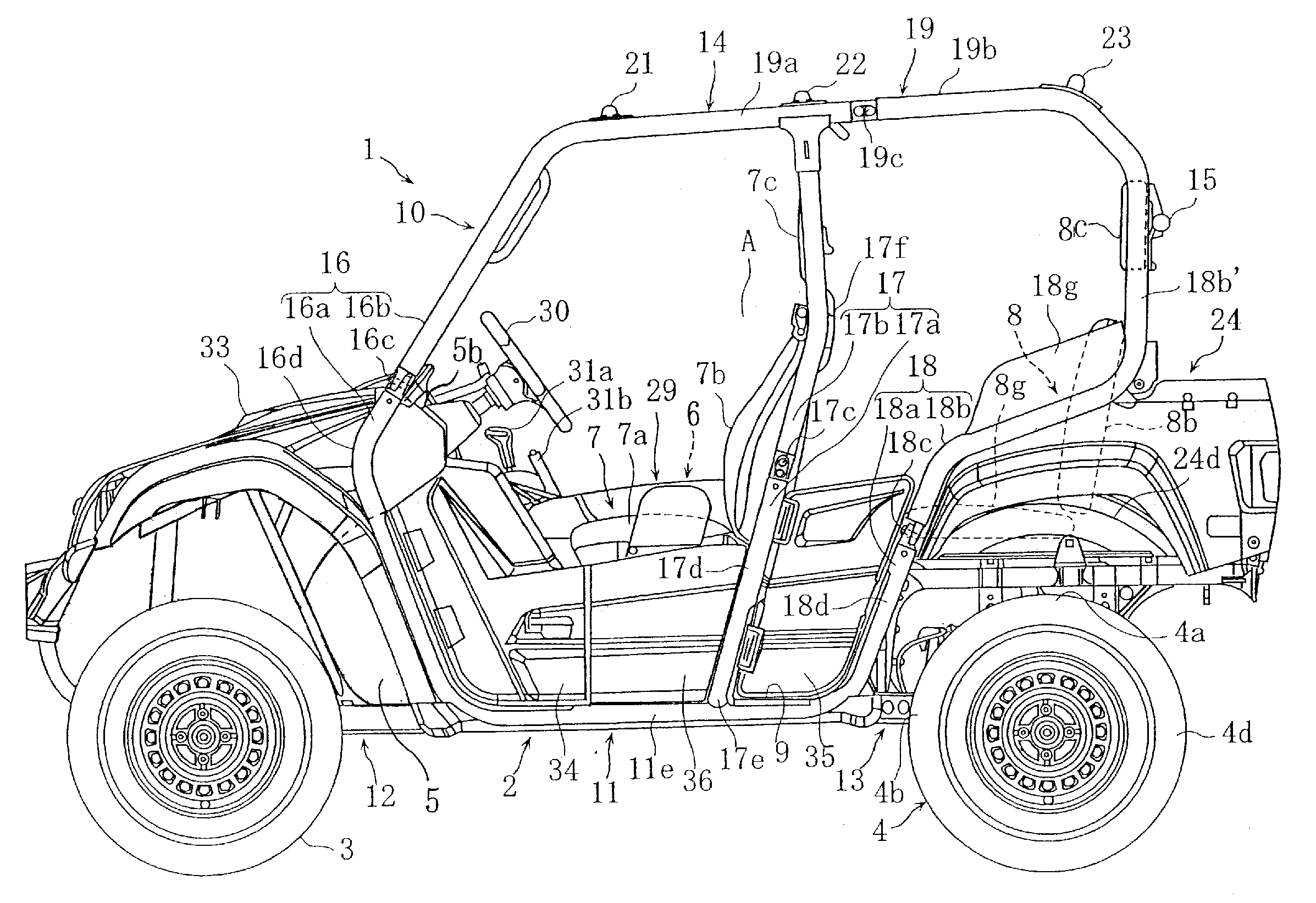
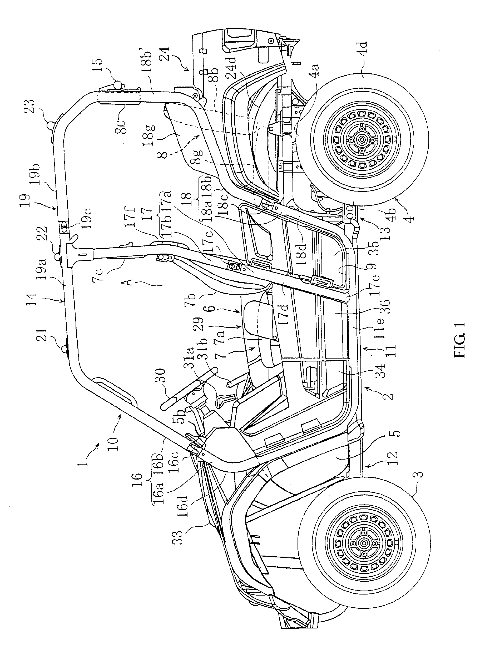
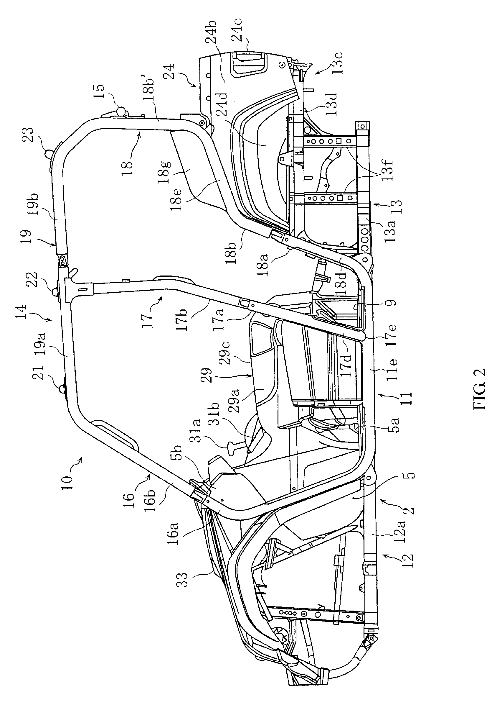
[0027]FIGS. 1 through 16 are drawings for explaining a utility vehicle in accordance with various exemplary embodiments of the present invention. Unless otherwise indicated the terms “front,”“behind,”“forward,”“back,”“rear,”“left,” and “right” refer to “front,”“behind,”“forward,”“back,”“rear,”“left,” and “right” are from the perspective of a passenger seated in a seat.

[0028]Referring to the figures generally, a utility vehicle 1 is provided with a vehicle body frame 2, a pair of left and right front wheels 3 that are supported on the left and right side portions at the forward portion of the vehicle body frame 2 and a pair of left and right rear wheels 4 that are supported on the left and right side portions of the rear portion Utility vehicle 1 also includes a front panel 5 that is disposed to the rear of the front wheels 3 of the vehicle body fr...


PUM


Abstract

A utility vehicle including: a vehicle body frame having a left and right side portion; a front seat affixed to the vehicle body frame; a rear seat affixed to the vehicle body frame provided to the rear of the front seat; a rear floor affixed to the vehicle body frame provided between the front seat and the rear seat; a first roof support structure including a first left member and first right pipe member that extend generally in the vertical direction from the vehicle body frame, disposed respectively at the left and right side portions of the vehicle body frame in front of the front seat; a second roof support structure including a second left member and a second right pipe member that extend generally in the vertical direction from the vehicle body frame, disposed respectively at the left and right side portions of the vehicle body frame to the rear of the front seat, wherein at least a portion of the second left pipe member and second right pipe member are positioned lower than a seating surface of a seat cushion portion of the rear seat and are angled so as to be positioned further towards the front seat; a third roof support structure including a third left member and third right pipe member that extend generally in the vertical direction from the vehicle body frame, disposed respectively at both the left and right side portions of the vehicle body frame to the rear of the rear seat, wherein at least a downward direction portion of the third left pipe member and third right pipe member are positioned lower than the seating surface of the seat cushion portion of the rear seat and are angled so as to be positioned further towards the back the higher up; and a roof member that connects to an upper portion of the first roof support structure, an upper portion of the second roof support structure, and an upper portion of the third roof support structure.

Description

[0001]This is a continuation-in-part application of Ser. No. 12 / 017,865 filed on Jan. 22, 2008 (pending).FIELD OF THE INVENTION[0002]The present invention relates to an improved design for a utility vehicle that allows improved ingress / egress for passengers.BACKGROUND OF THE INVENTION[0003]Utility vehicles with more than one row of seating are known in the art. Among this type of vehicle there are vehicles that have a front seat and a rear seat, provided behind the front seat, as seats wherein the passengers sit. For example, U.S. Pat. No. 7,249,798 discloses a utility vehicle with an upper portion of the cabin structured by connecting together the top portions of a plurality of roof support structures using roof members, producing a cabin with a feeling of spaciousness, while having a front seat and a rear seat.[0004]However, while this type of conventional vehicle has a wide cabin, the rear floor extends forward and backward in order to increase the ease of ingress / egress of the p...

Claims


Application Information

Patent Timeline
IPC IPC(8): B62D33/06B60N2/005
CPCB60N2/005B60N2/06B60N2/3011B62D25/04B60N2/4802B60N2/686B62D23/005B60N2/305B60N2/803
Inventor YAMAMURA, TAKASHISMITH, CRAIG
Owner YAMAHA MOTOR CO LTD
Why Eureka
Try Eureka