Liquid jet head, a liquid jet apparatus and a method for manufacturing a liquid jet head

a liquid jet and head technology, applied in the direction of printing, other printing apparatus, etc., can solve the problems of limited heat dissipation ability, difficult miniaturization damage to the driving circuit, so as to improve the durability of the driving circuit, improve the liquid ejection characteristics, and effectively dissipate heat from the driving circuit

Active Publication Date: 2009-07-23
SEIKO EPSON CORP
View PDF5 Cites 2 Cited by
  • Summary
  • Abstract
  • Description
  • Claims
  • Application Information

AI Technical Summary

Benefits of technology

[0011]The present invention has been made in view of such circumstances, and an object of the present invention is to provide a liquid jet head and a liquid jet apparatus capable of effectively dissipating heat from a driving circuit, achieving miniaturization and low cost for the driving circuit, and improving the durability of the driving circuit, thereby improving the liquid ejection characteristics. In accordance with an aspect of the present invention, in order to solve the problems, there is provided a liquid jet head which includes: a pressure generation unit that causes pressure change in pressure generation chambers which are communicated with nozzle openings that eject liquid; a driving unit that generates a driving signal for driving the pressure generation unit; a case head that accommodates therein the driving unit; and a thermally conductor that is in contact with the driving unit and the case head, in which the thermally conductor and the case head are fixed to each other via a thermally conductive layer.

Problems solved by technology

However, the driving circuit mounted on the flexible printed circuit board is only able to dissipate heat from the driving circuit per se, the heat dissipation ability is limited.
When a circuit loss exceeds the heat dissipation ability, the driving circuit may be destroyed by heat.
Moreover, since a large heat dissipation area is required for securing the heat dissipation properties, there is a problem that miniaturization of the driving circuit is difficult.
Particularly, when the driving circuit is provided inside the case head as disclosed in Patent Document 1, the driving circuit is only able to dissipate heat within the case head and unable to dissipate the heat to the atmosphere, and thus the temperature of the driving circuit increases.
Such problems are similarly found in other liquid jet heads ejecting liquid other than ink as well as the ink jet recording head.

Method used


Image

  • Liquid jet head, a liquid jet apparatus and a method for manufacturing a liquid jet head
  • Liquid jet head, a liquid jet apparatus and a method for manufacturing a liquid jet head
  • Liquid jet head, a liquid jet apparatus and a method for manufacturing a liquid jet head

Examples


embodiment 1

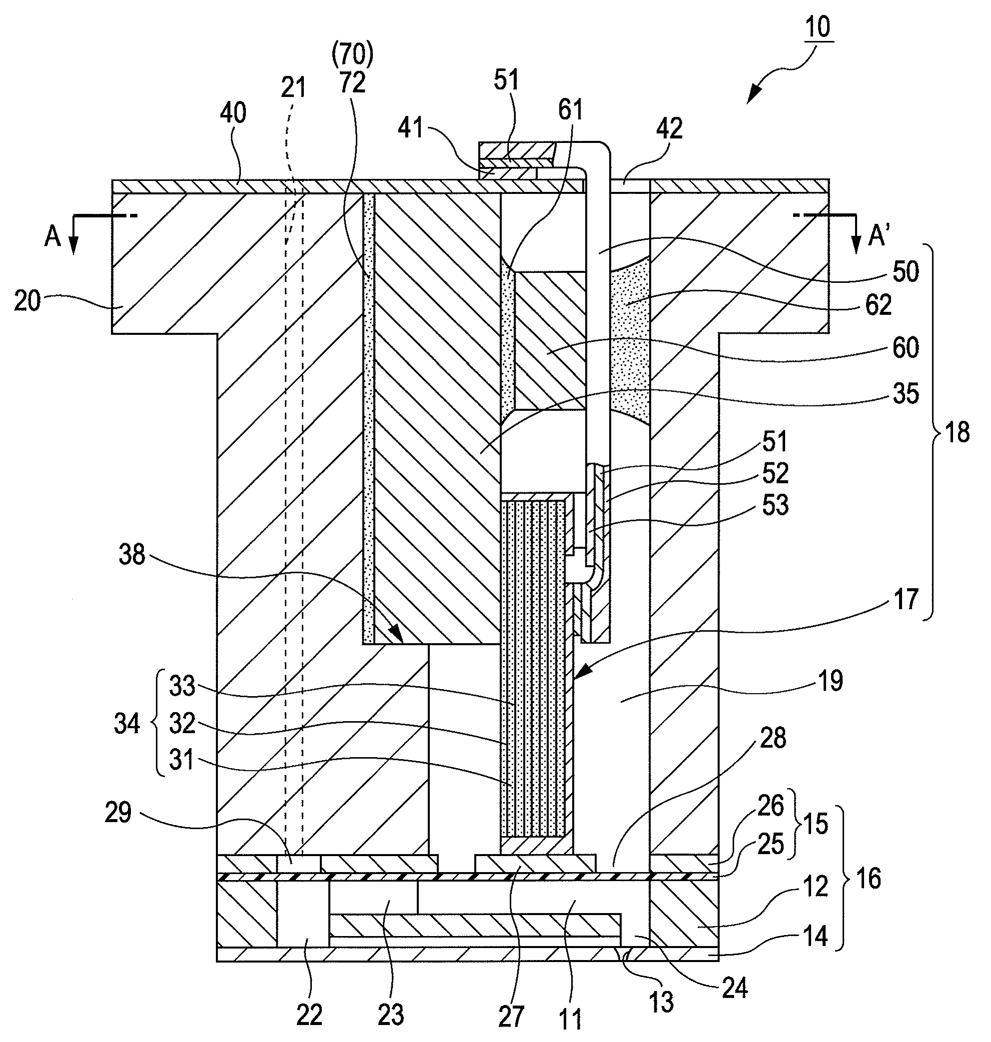
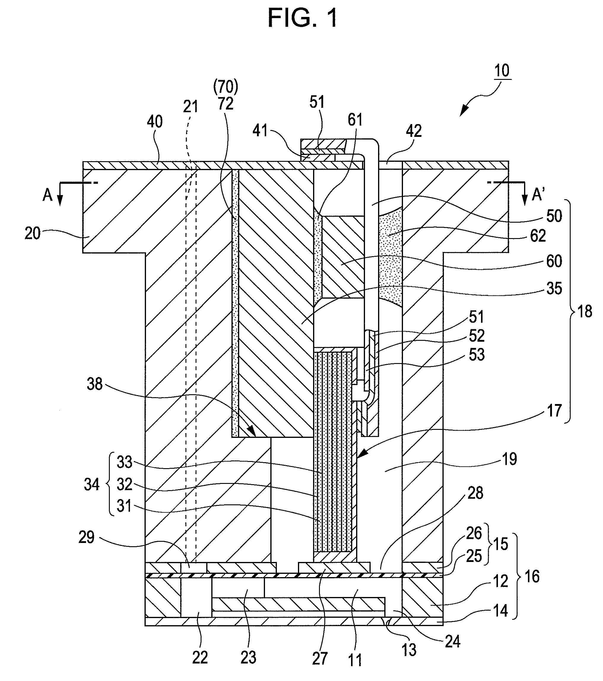
[0047]FIG. 1 is a cross-sectional view of an ink jet recording head 10 which is an example of a liquid jet head according to a first embodiment of the present invention. FIG. 2 is a cross-sectional view taken along the line A-A′ in FIG. 1.

[0048]As illustrated in the drawings, the ink jet recording head 10 has a flow path unit 16 which is provided with a flow path forming board 12 having therein a plurality of pressure generation chambers 11, a nozzle plate 14 in which a plurality of nozzle openings 13 is formed to be communicated with the pressure generation chambers 11, and a vibration plate 15 which is provided on a surface of the flow path forming board 12 opposite to the nozzle plate 14. Further, the ink jet recording head 10 is provided with a piezoelectric element unit 18 which has piezoelectric elements 17 provided on a region of the vibration plate 15 correspond to respective one of the pressure generation chambers 11 and a case head 20 which has an accommodation portion 19 ...

embodiment 2

[0091]FIG. 5 is a cross-sectional view of an ink jet recording head 10a according to this embodiment, in which the case head 20 and the thermally conductor 35 are connected to each other via the thermally conductive adhesive layer 72 as the thermally conductive layer. In the present embodiment, the thermally conductive adhesive layer 72 as the thermally conductive layer is formed over the entire surface in which the case head 20 and the thermally conductor 35 are connected to each other.

[0092]By doing so, the heat generated from the driving circuit 60 can be effectively conducted from the thermally conductor 35 to the case head 20.

[0093]Next, the manufacturing method for fixing the case head 20 and the piezoelectric element unit 18 according to the present embodiment will be described. FIG. 6 is a view describing the manufacturing method for fixing the case head 20 and the piezoelectric element unit 18 according to the present embodiment.

[0094]As described in the first embodiment, t...

embodiment 3

[0100]FIG. 7 is a cross-sectional view of an ink jet recording head 10b which is provided with the thermally conductive adhesive layer 72 at a position opposing the thermally conductor 35. As illustrated in FIG. 7, the case head 20 is formed with ribs 39a which are configured to project toward the thermally conductor 35, and the ribs 39a make abutting contact with the thermally conductor 35.

[0101]In the present embodiment, the thermally conductive adhesive layer 72 is formed at a position which is located in a region sandwiched by the two ribs 39a formed above and below in the drawing, respectively, and to which the driving circuit 60 is opposed with the thermally conductor 35 disposed between them. By doing so, the heat generated from the driving circuit 60 can be effectively conducted from the thermally conductor 35 to the case head 20.


PUM


Abstract

An ink jet recording head 10 is provided which includes: piezoelectric elements 17 as a pressure generation unit that causes pressure change in pressure generation chambers 11 which are communicated with nozzle openings 13 that eject liquid; a driving circuit 60 as a driving unit that generates a driving signal for driving the pressure generation unit; a case head 20 that accommodates therein the driving unit; and a thermally conductor 35 that is in contact with the driving unit and the case head 20, in which the thermally conductor 35 and the case head 20 are fixed to each other via an thermally conductive adhesive layer 72 as a thermally conductive layer.

Description

[0001]The entire disclosure of Japanese Patent Application No. 2008-006515, filed Jan. 16, 2008 is incorporated by reference herein.[0002]The entire disclosure of Japanese Patent Application No. 2009-003243, filed Jan. 9, 2009 is incorporated by reference herein.BACKGROUND OF THE INVENTION[0003]1. Field of the Invention[0004]The present invention relates to a liquid jet head, a liquid jet apparatus, and a method for manufacturing the liquid jet head.[0005]2. Description of the Related Art[0006]As a typical example of a liquid jet head, for example, there is known an ink jet recording head that ejects ink droplets from nozzle openings by using pressure change caused by displacement of piezoelectric elements. Specifically, as disclosed in JP-A-2004-074740, an ink jet recording head is known which includes: a flow path unit which has a flow path forming board having therein pressure generation chambers, which are communicated with nozzle openings, and a vibration plate provided on one ...

Claims


Application Information

Patent Timeline
Patent Type & Authority Applications(United States)
IPC IPC(8): B41J2/045
CPCB41J2/14274B41J2002/14362B41J2/1623B41J2/1612
Inventor ITO, SUKEHIRO
Owner SEIKO EPSON CORP
Why Eureka
Try Eureka