Integrated magnetics switching converter with zero inductor and output ripple currents and lossless switching

Inactive Publication Date: 2009-07-23
CUKS
View PDF13 Cites 43 Cited by
  • Summary
  • Abstract
  • Description
  • Claims
  • Application Information

AI Technical Summary

Benefits of technology

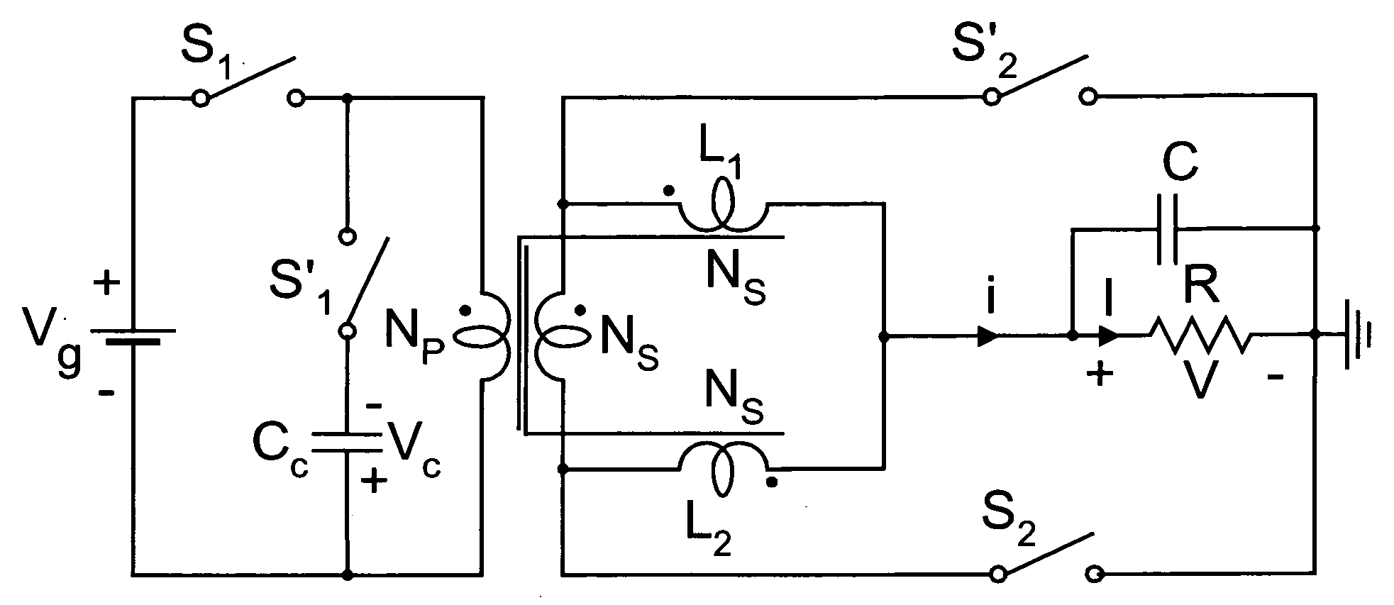
[0024]The switching converter of the present invention is shown in FIG. 9a with its Integrated Magnetics structure, the corresponding hard-switching drive control in FIG. 9b, and one preferred Integrated Magnetics embodiment in FIG. 9c. This converter combines the best performance characteristics of the above described conventional converters. The Integrated Magnetics structure shown in FIG. 9c has a special property that the two output inductors are directly coupled to the isolatio

Problems solved by technology

This results in more complex filter than in forward converter, as there are now two inductors instead of one.
How

Method used


Image

  • Integrated magnetics switching converter with zero inductor and output ripple currents and lossless switching
  • Integrated magnetics switching converter with zero inductor and output ripple currents and lossless switching
  • Integrated magnetics switching converter with zero inductor and output ripple currents and lossless switching

Examples


experimental verification

of Three Zero Ripple Currents

[0246]Experimental prototype was made to implement Integrated magnetics Circuit of FIG. 14a in order to confirm that both inductor currents and output current are zero simultaneously at one operating pint duty ratio of 0.5. FIG. 42a illustrates that all three ripple currents are zero and that magnetizing inductance ripple current is high. FIG. 42b illustrates that switch currents are also square-wave like and have no superimposed triangular ripple currents of inductors. FIG. 42c illustrates that isolation transformer secondary current is also square-wave like with no superimposed triangular ripple currents generated normally by two inductors.

[0247]When the operating point is moved to D=1 / 3, the output ripple current becomes non-zero. However, FIG. 43a proves that the output ripple current (third trace from top) is the sum of two inductor ripple currents (top two traces). FIG. 43b shows that output switch??? current also have much reduced superimposed rip...


PUM


Abstract

Switching Converter with a novel two-loop Integrated magnetic structure integrates transformer and two output inductors and eliminates large circulating current in the transformer secondary side resulting in ultra high efficiency and zero ripple output current as well as zero ripple currents in both output inductors simultaneously. The novel lossless switching method eliminates the primary side switching losses to result in switching converter with highest efficiency, compact size and additional performance advantages, such as ultra low output ripple voltage, low EMI noise and improved reliability with additional benefits when operated with a front-end Power Factor Converter for computer server applications.

Description

CROSS-REFERENCE TO RELATED APPLICATIONS[0001]Provisional U.S. Patent Application No. 61 / 011,512[0002]Filed on Jan. 18, 2008[0003]Applicant: Slobodan Cuk[0004]Title: Switching Converter with New Integrated Magnetics and Zero Ripple Currents[0005]Confirmation Number: 5365[0006]Provisional U.S. Patent Application No. 60 / 937,906[0007]Filed on Jun. 30, 2007[0008]Applicant: Slobodan Cuk[0009]Title: Integrated Magnetics Zero-ripple Switching Converter[0010]Confirmation Number: 2501FIELD OF THE INVENTION[0011]This invention relates to the field of switching DC-to-DC power conversion and in particular to the class of isolated switching converters capable of obtaining zero ripple output current at 50% duty ratio and consisting of switches, an isolation transformer and two output filtering inductors. This invention also extends the operation at zero ripple output currents to duty ratios other than 50% heretofore not available in other switching DC-to-DC converters while preserving efficiency a...

Claims


Application Information

Patent Timeline
IPC IPC(8): H02M3/335
CPCH02M1/34H02M3/33507Y02B70/1491H02M2001/342H02M3/33576H02M1/342Y02B70/10
Inventor CUK, SLOBODAN
Owner CUKS
Why Eureka
Try Eureka