Wind-driven electricity generation device, method of controlling wind-driven electricity generation device, and computer program

a technology of wind-driven electricity and generation device, which is applied in the direction of rotors, vessel construction, marine propulsion, etc., can solve the problems of blade breakage, blade breakage, and limit the durability of an outside force accompanying a wind power, so as to and reduce the breakage of the blad

Inactive Publication Date: 2009-07-23
THE TOKYO ELECTRIC POWER CO INC
View PDF0 Cites 44 Cited by
  • Summary
  • Abstract
  • Description
  • Claims
  • Application Information

AI Technical Summary

Benefits of technology

[0093]According to the inventions described in claims 1 to 4, it becomes possible to provide a wind power generation device capable of reducing breakage of a blade due to a flying object or bird strike.
[0094]In addition, according to the inventions described in claims 5 to 7, it becomes possible to provide a control process for the wind power generation device capable of reducing breakage of the blade due to a flying object or bird strike.
[0095]Furthermore, according to the inventions described in claims 8 to 10, it becomes possible to provide a control program for the wind power generation device capable of reducing breakage of the blade due to a flying object or bird strike.
[0096]Still further, according to the inventions described in claims 11 to 13, in addition to the above-described objects of the inventions, it becomes possible to provide a technology relating to the wind power generation device capable of reducing a breakage accident of the blade due to gusts.

Problems solved by technology

However, even in any wind power generation device, there is a limitation of durability to an outside force accompanying a wind power.
Meanwhile, because of difficulty for flying birds to visually recognize blades rotating at a high speed, accidents (bird strike) of collision against blades into death happen.
Furthermore, the device is provided with an anemometer and an anemoscope as shown in FIG. 10, but these are only for an ex post measurement, and a flying object blown off by a strong wind collides against a blade, which may result in breakage of the blade.

Method used


Image

  • Wind-driven electricity generation device, method of controlling wind-driven electricity generation device, and computer program
  • Wind-driven electricity generation device, method of controlling wind-driven electricity generation device, and computer program
  • Wind-driven electricity generation device, method of controlling wind-driven electricity generation device, and computer program

Examples


first embodiment

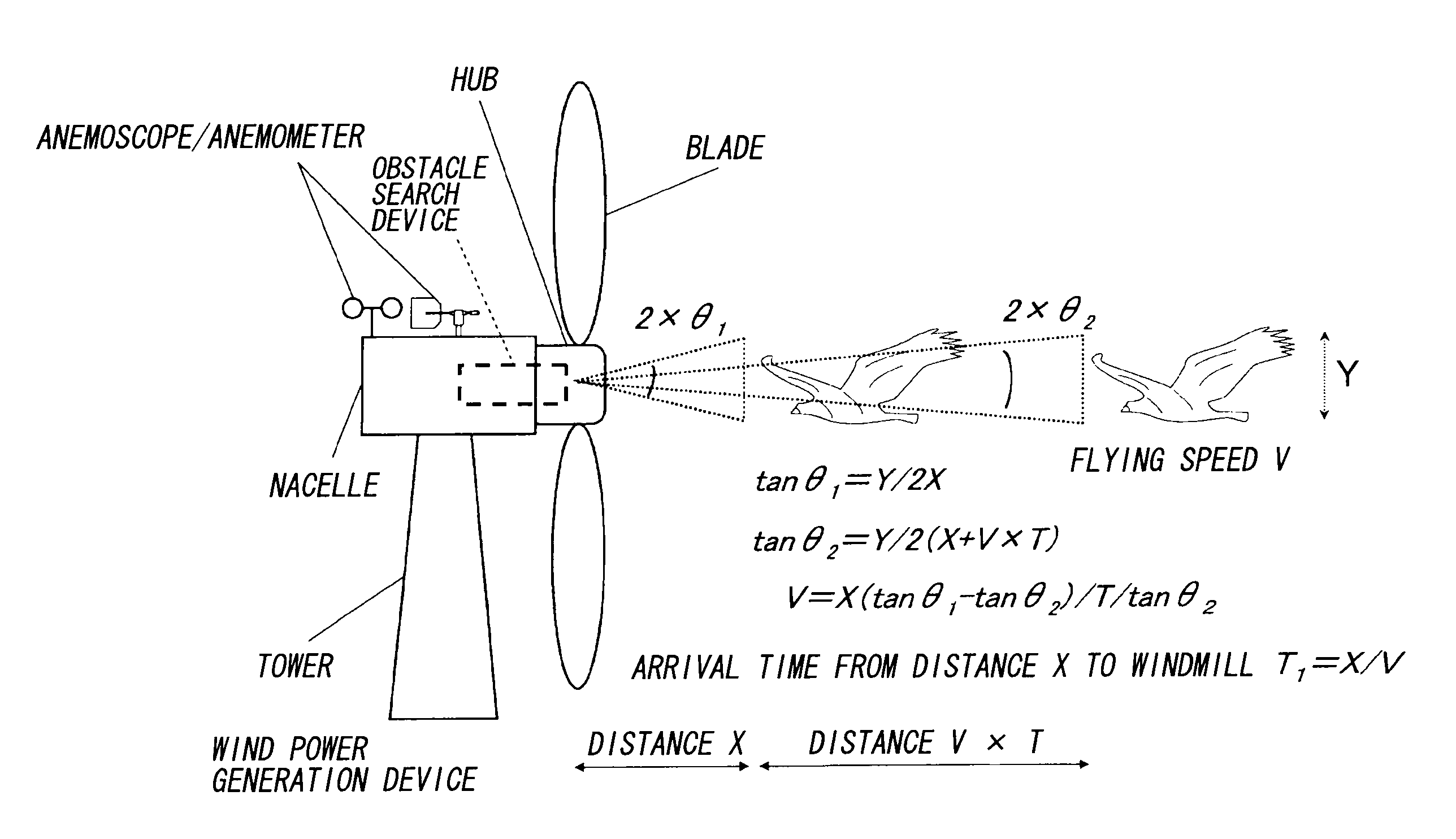
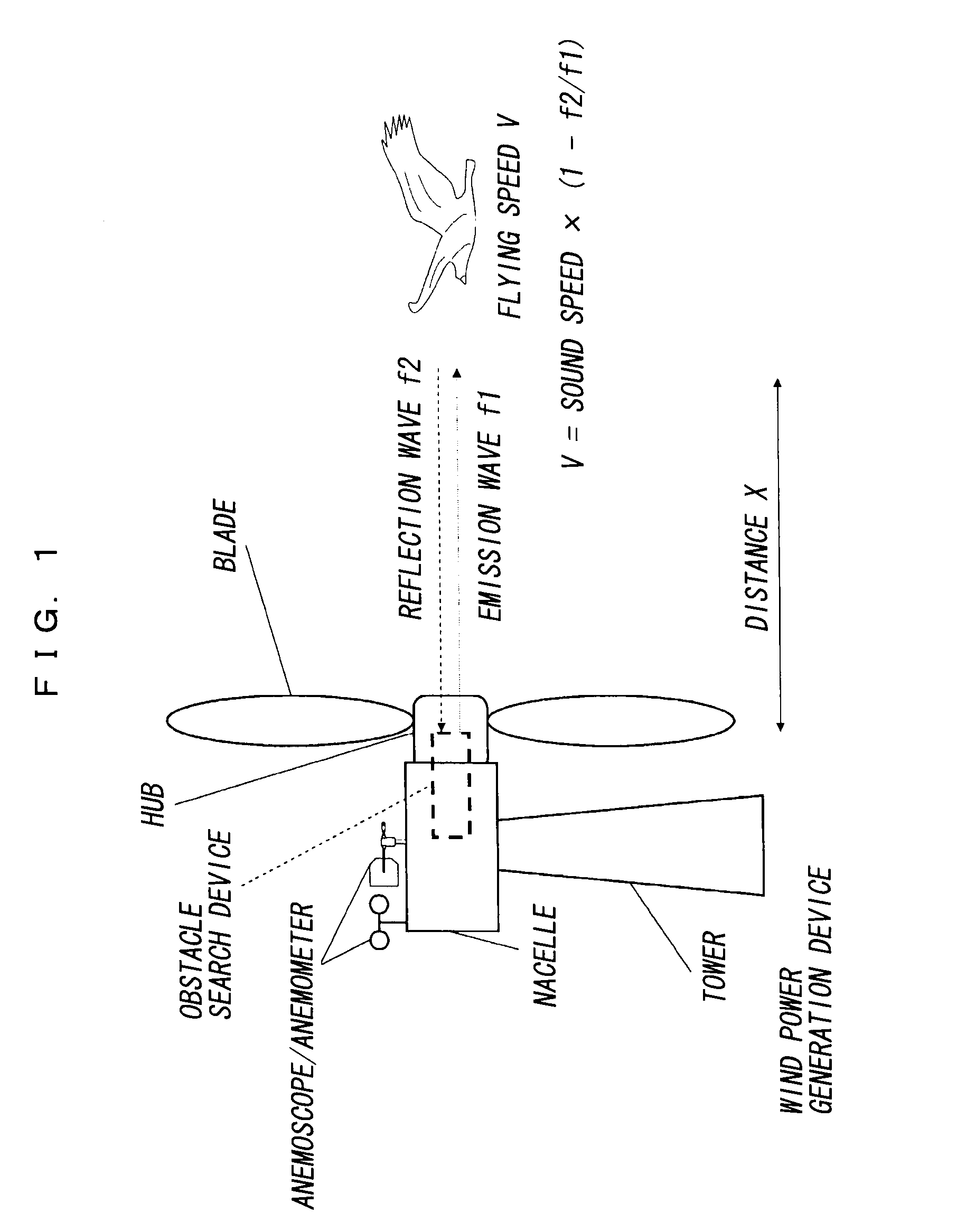
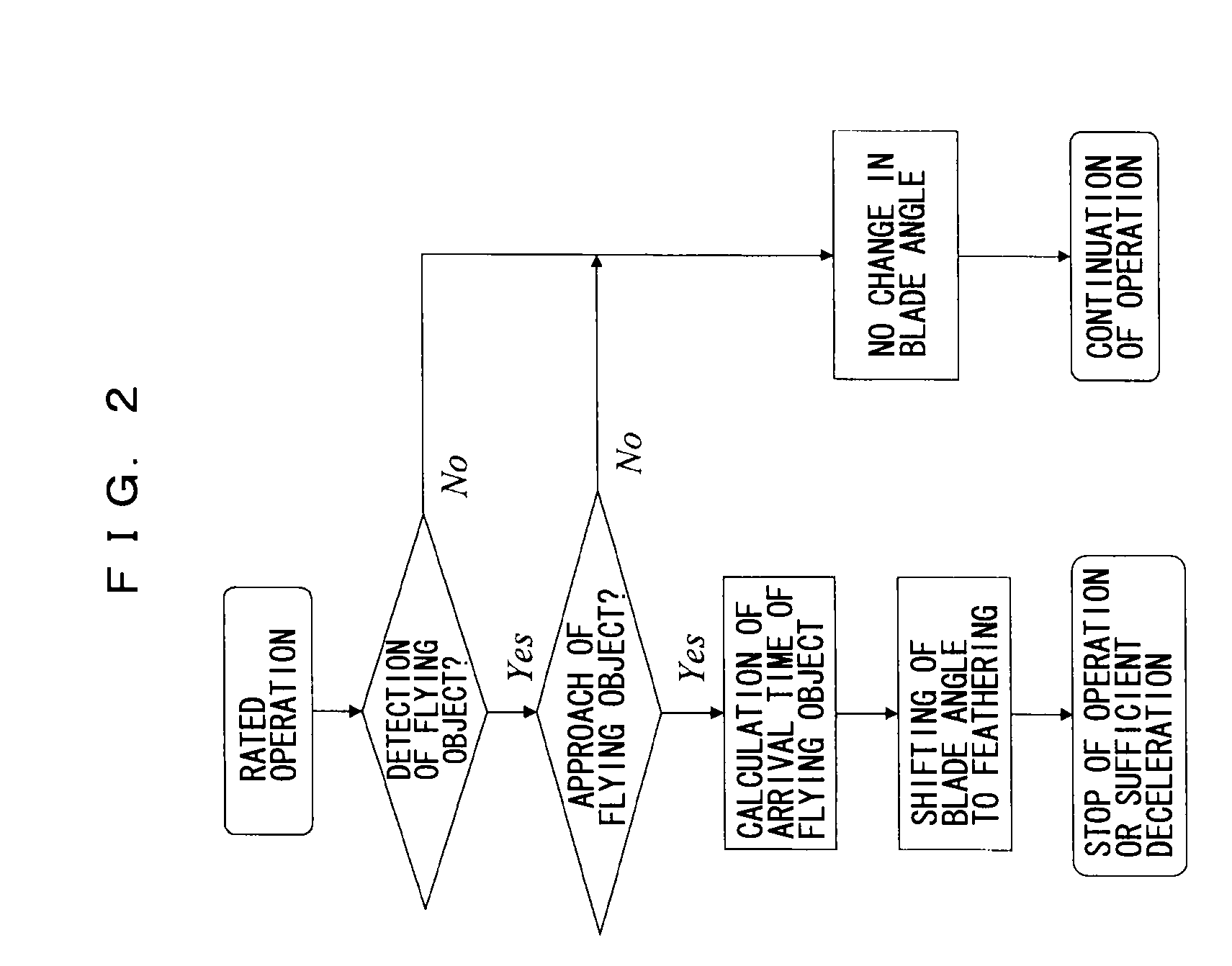
[0108]The first embodiment shown in FIG. 1 relates to a wind power generation device including a tower set up on the ground, a nacelle fixed on the tower, a plurality of blades rotatably fixed to the nacelle via a hub, an obstacle search device capable of detecting the flying object in front, on the windward side, and a blade angle controller to control change in the blade angle including a rotation stop position.

[0109]As for the obstacle search device, adopted is not a device to ascertain the presence of the flying object based on the image pickup and the image analysis, but a device to ascertain the presence of the flying object by oscillating a sonic wave or an electromagnetic wave and seizing its reflection wave.

[0110]Note that when a thermal detector is used, though it can detect only the flying object such as a living creature like birds having a higher temperature than its surrounding temperature, it has an advantage that at night or under a bad weather such as driving snow, ...


PUM


Abstract

The present invention provides a wind power generation device capable of reducing collision of a flying object against a blade or bird strike. The wind power generation device includes a tower set up on the ground, a nacelle fixed to the tower, a plurality of blades rotatably fixed to the nacelle via a hub, an obstacle search device capable of detecting a flying object existing in front, on the windward side, and a blade angle controller to control the change in angle of the blade including a rotation stop position. The obstacle search device searches for the flying object continuously, and when the flying object is determined to be approaching based on the continuous searching, the blade angle controller controls to change the blades to the rotation stop position.

Description

TECHNICAL FIELD[0001]The present invention relates to a technology to avoid occurrence that a flying object collides against a blade when the flying object (mainly, birds) is approaching to wind power generation device, and technologies relating thereto.BACKGROUND ART[0002]In a place to install a wind power station, in order to know wind conditions, wind speed and wind direction are measured.[0003]For instance, a Doppler sodar (Doppler sonic radar) oscillates a sonic wave having a fixed frequency of several thousands Hz toward air at intervals of several seconds from an arbitrary place in situ. The sonic wave collides against particles such as water vapor, dusts or the like contained in the wind in the air and reflects. The reflection wave is caught with a large cylindrical body and wind speed thereof is calculated based on the reflection wave modulated due to a Doppler effect. It is possible to calculate a wind direction by using about three pieces of cylindrical bodies for receivi...

Claims


Application Information

Patent Timeline
Patent Type & Authority Applications(United States)
IPC IPC(8): F03D7/00
CPCF03D7/0264F03D7/042F03D11/0091F05B2260/821Y02E10/723F05B2270/8041F05B2270/805Y02E10/722F05B2270/107F03D17/00Y02E10/72
Inventor HIRAKATA, NAOTOTEZUKA, HIDEAKI
Owner THE TOKYO ELECTRIC POWER CO INC
Why Eureka
Try Eureka