Contamination prevention in extreme ultraviolet lithography

a technology of ultraviolet light and contamination prevention, applied in the field of particle contamination prevention, can solve the problems of insufficient use of conventional transmission masks, inability to protect masks, and inability to print even small device structures at the same tim

Inactive Publication Date: 2009-07-23
APPLIED MATERIALS INC
View PDF21 Cites 10 Cited by
  • Summary
  • Abstract
  • Description
  • Claims
  • Application Information

AI Technical Summary

Problems solved by technology

As the trend continues to reduce the size of semiconductor devices, optical lithography using conventional transmission masks, such as chrome on glass (COG) or phase shift (PSM) masks, will no longer suffice as a viable technique for printing advanced devices on semiconductor wafers.
However, the still shorter wavelengths necessary for printing even

Method used


Image

  • Contamination prevention in extreme ultraviolet lithography
  • Contamination prevention in extreme ultraviolet lithography
  • Contamination prevention in extreme ultraviolet lithography

Examples


Embodiment Construction

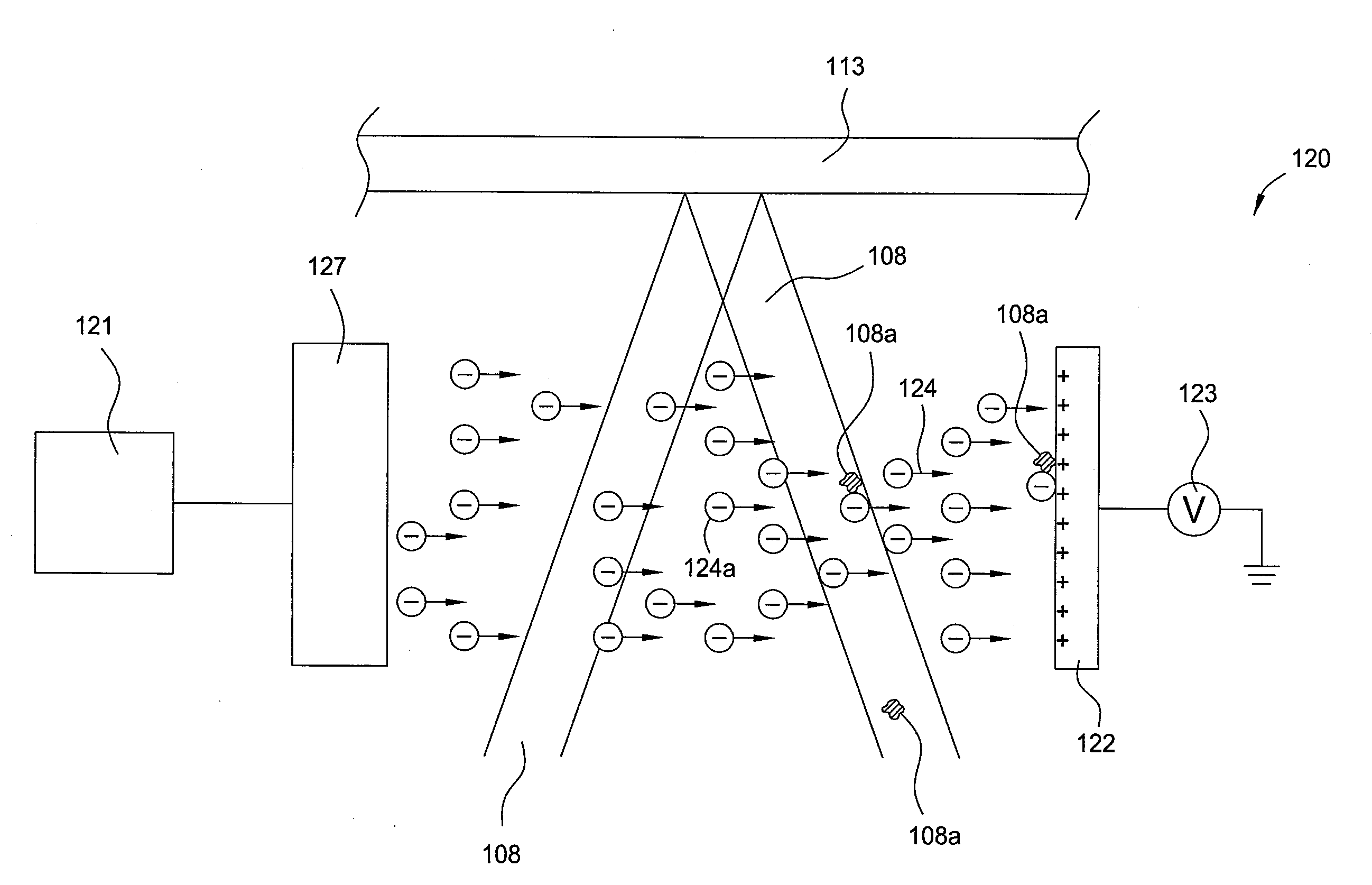
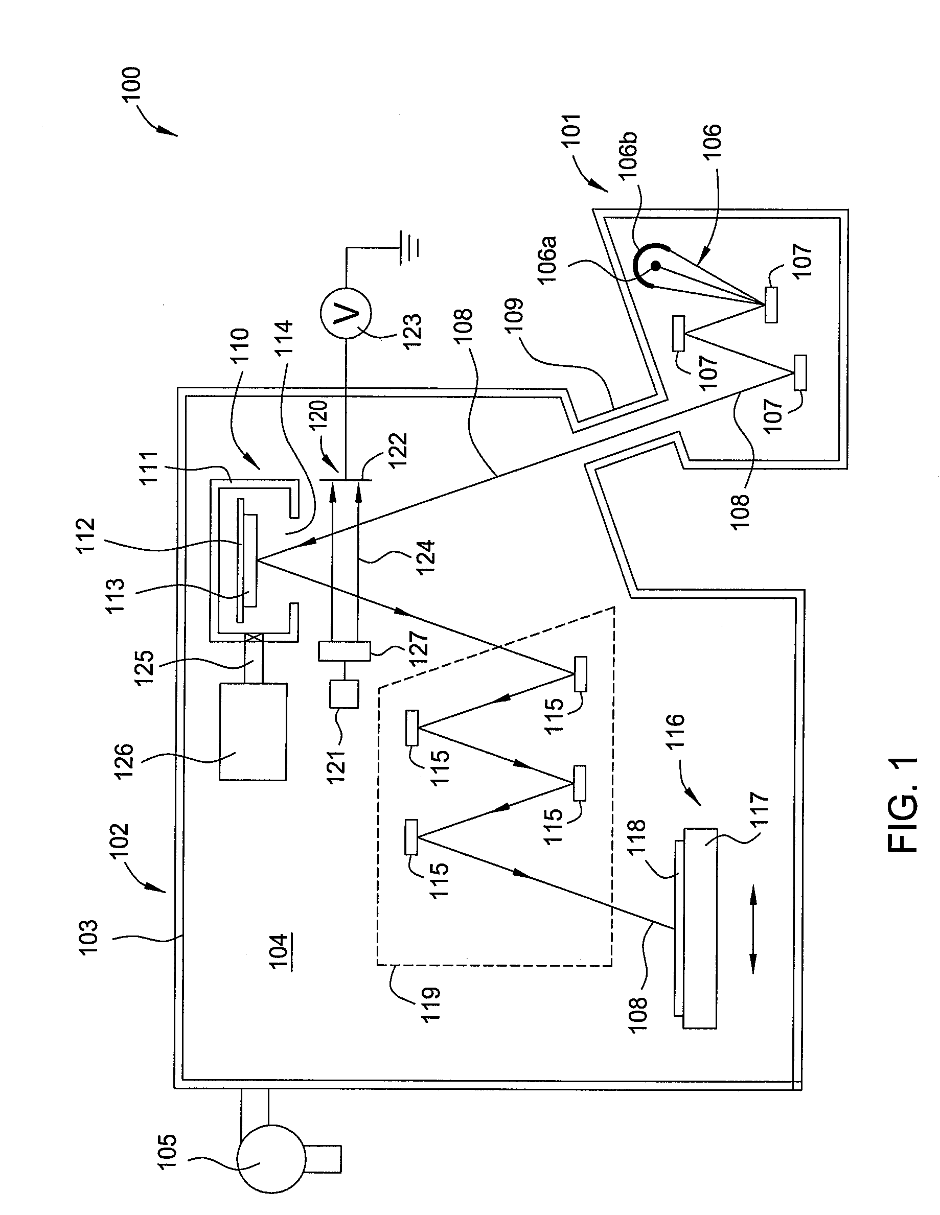
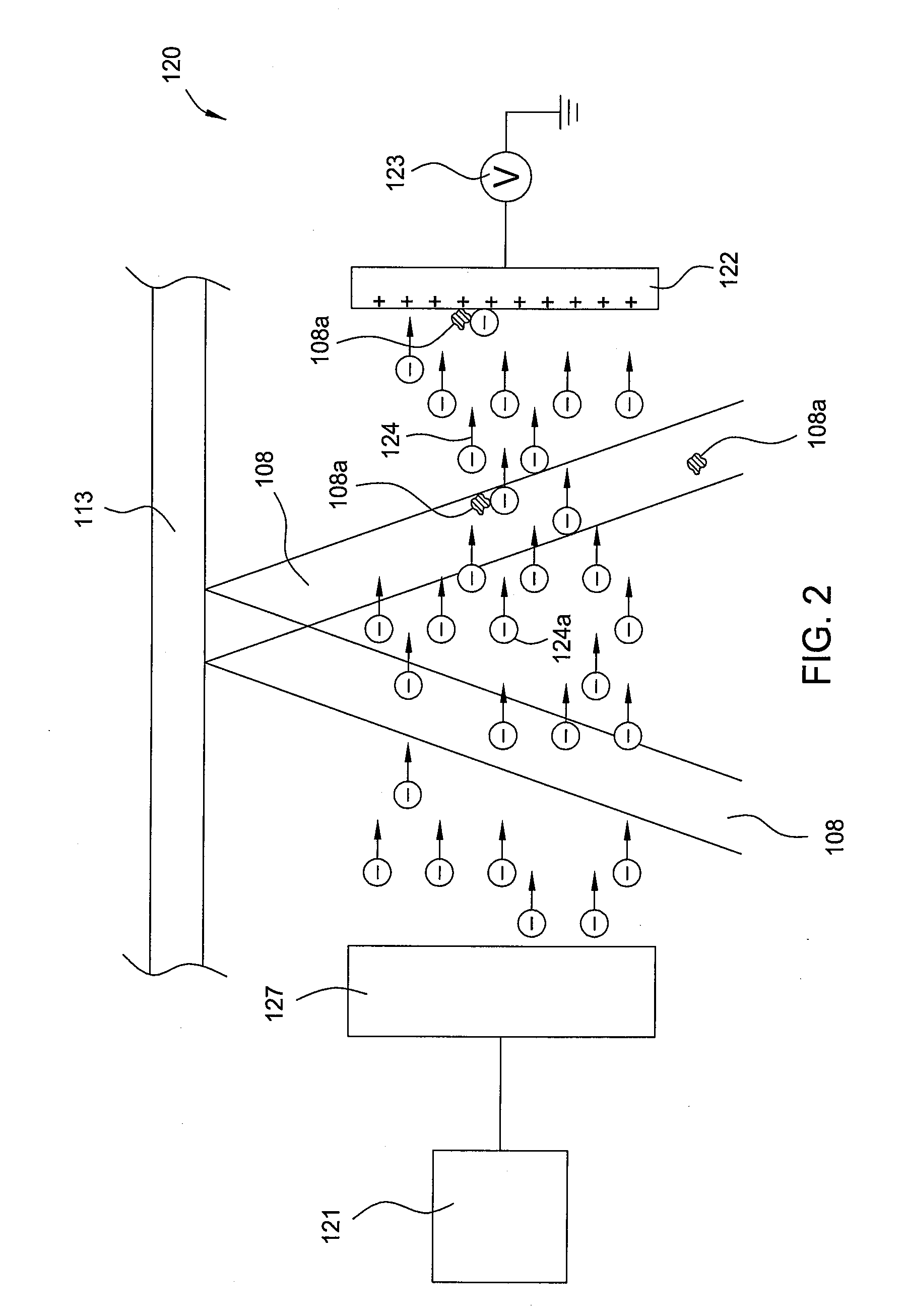
[0017]Embodiments of the present invention generally provide apparatus and method for preventing particle contamination during lithography. Particularly, embodiments of the present invention provide methods and apparatus for removing debris particles from a beam of radiation during photolithography.

[0018]In one embodiment, a charged species source and a collecting plate are disposed on opposite sides of a beam of radiation used in lithography. The charged species source is configured to project a stream of charged species and the collecting plate is configured to receive the stream of charged species from the charges species source. The stream of the charged species is configured to intersect the beam of radiation, and to use electrostatic force to remove debris particles from the beam of radiation, thus, preventing the debris particles from contaminating the mask, the substrate being processed, and any devices in the path of the beam of radiation. The charged species source and the...


PUM


Abstract

Embodiments of the present invention provide methods and apparatus for removing debris particles using a stream of charged species. One embodiment of the present invention provides an apparatus for removing debris particles from a beam of radiation comprising a charged species source configured to dispense electrically charged species, and a collecting plate biased electrically opposite to the charged species from the charged species source, wherein the collecting plate and the charged species source are disposed on opposite sides of the beam of radiation, a stream of charged species from the charged species source to the collecting plate intersects the beam of radiation, the stream of charged species is configured to attach and remove debris particles from the beam of radiation by electrostatic force, and the collecting plate is configured to receive the charged species and the debris particles removed from the beam of radiation.

Description

BACKGROUND[0001]1. Field[0002]Embodiments of the present invention generally relate to methods and apparatus for preventing particle contamination. Particularly, embodiments of the present invention provide methods and apparatus for protecting masks and / or substrates during lithography.[0003]2. Description of the Related Art[0004]As the trend continues to reduce the size of semiconductor devices, optical lithography using conventional transmission masks, such as chrome on glass (COG) or phase shift (PSM) masks, will no longer suffice as a viable technique for printing advanced devices on semiconductor wafers. Transmission lithography has been extended to ever shorter wavelengths, down to 157 nm in the far ultraviolet (UV), in order to reduce the size of device features. However, the still shorter wavelengths necessary for printing even smaller device structures are readily absorbed in transmission materials. Alternative technological candidates to replace optical lithography include...

Claims


Application Information

Patent Timeline
IPC IPC(8): G03F1/14H01J37/08
CPCG03F7/70916G03F7/70858
Inventor WU, BANQIUKUMAR, AJAY
Owner APPLIED MATERIALS INC
Why Eureka
Try Eureka