Eureka AIR delivers breakthrough ideas for toughest innovation challenges, trusted by R&D personnel around the world.

Ultrasound imaging apparatus and a method for generating an ultrasound image

Inactive Publication Date: 2009-07-23
TOSHIBA MEDICAL SYST CORP
View PDF3 Cites 6 Cited by
  • Summary
  • Abstract
  • Description
  • Claims
  • Application Information

AI Technical Summary

Benefits of technology

[0015]The present invention has been devised to provide an ultrasound imaging apparatus capable of improving the real-time properties of the image representing a puncture needle while acquiring an image representing a puncture object and a method of generating ultrasound images.
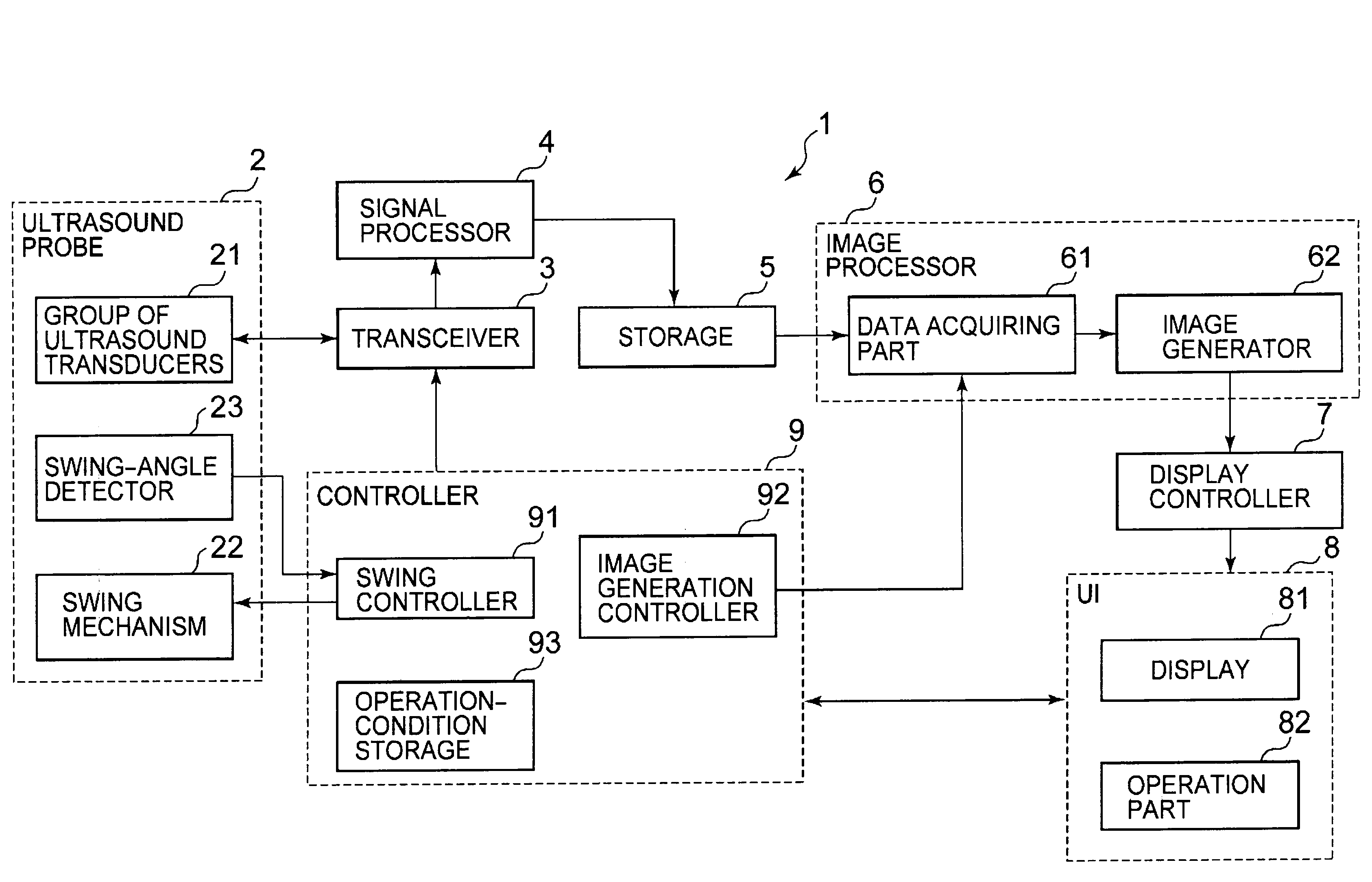
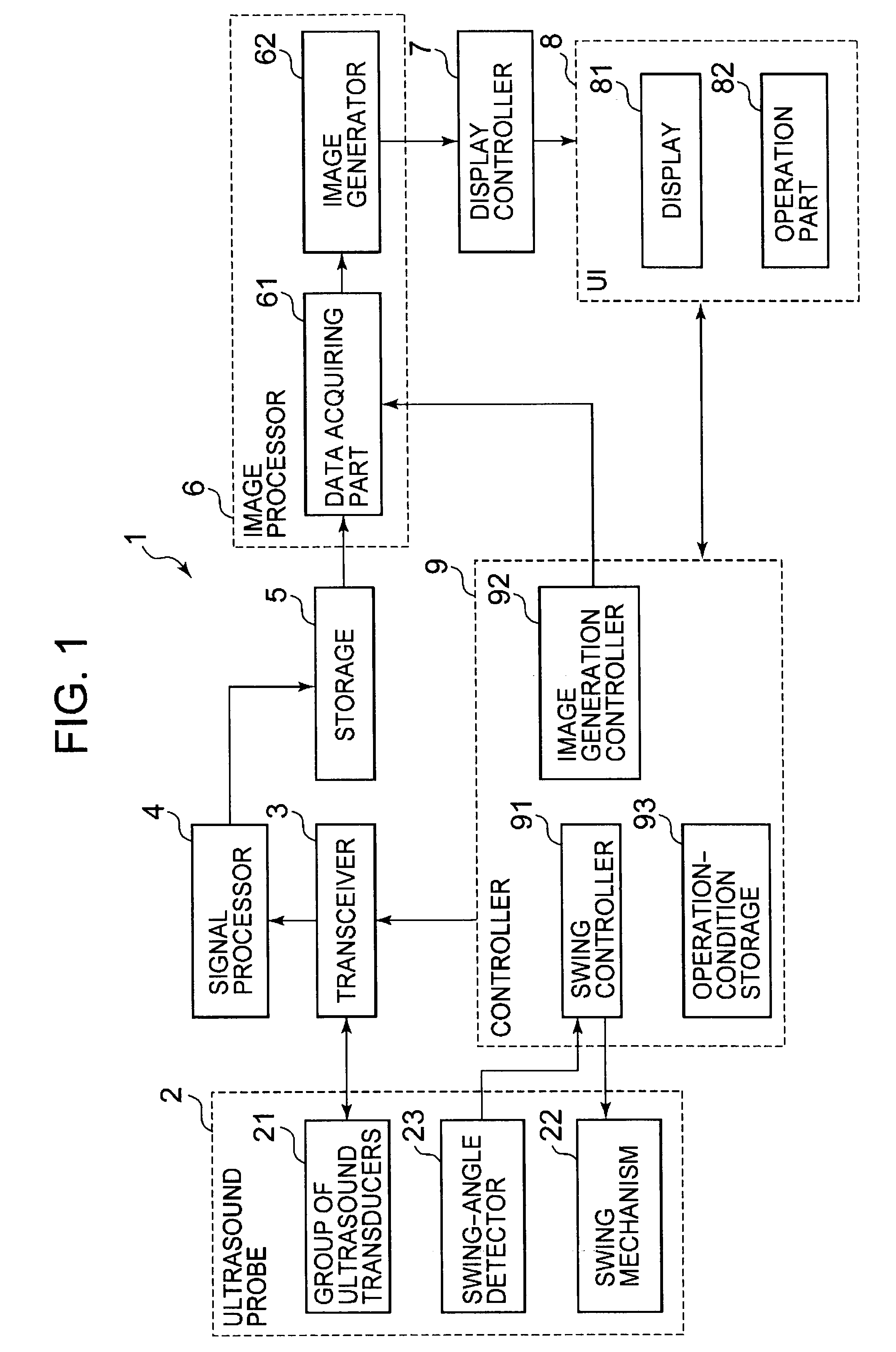
[0017]According to the first aspect, the rate for updating the volume data in the second scanning region becomes faster by consecutively scanning the second scanning region more than once. Therefore, it becomes possible to improve the real-time properties of an ultrasound image in the second scanning region. Furthermore, it becomes possible to acquire the entire image of an imaging subject by scanning the first scanning region that is larger than the second scanning region. It becomes possible to improve the real-time properties of an ultrasound image representing a puncture needle while acquiring and displaying the ultrasound image representing a puncture object that is included in the first scanning region by including the puncture needle in the second scanning region.

Problems solved by technology

However, the number of swings of the ultrasound transducer per unit time decreases, with the result that there is a problem that the volume rate becomes lower.
Consequently, it becomes difficult to acquire and display in real time a three-dimensional image or MPR image in which a puncture needle is represented, so that it is difficult to track the position of the puncture needle in real time.

Method used


Image

  • Ultrasound imaging apparatus and a method for generating an ultrasound image
  • Ultrasound imaging apparatus and a method for generating an ultrasound image
  • Ultrasound imaging apparatus and a method for generating an ultrasound image

Examples


first operation example

[0093]First, a first operation example will be described with reference to FIG. 5. FIG. 5 is a conceptual view for explaining the first operation example according to the ultrasound imaging apparatus according to the embodiment of the present invention. In a graph shown in FIG. 5, the horizontal axis takes time t, and the vertical axis takes a swing angle. In FIG. 5, timing of data acquisition in each scanning region, data subjected to image generation, and timing for updating the display are shown.

[0094]In the first operation example, scan is performed in a state where a swing speed for swinging the group of ultrasound transducers 21 is kept constant and the widths of the range of the swing angle in the second scanning region V2 (range from −α degree to +α degree), the range of the swing angle in the third scanning region V3 (range from +α degree to +β degree) and the range of the swing angle in the fourth scanning region V4 (range from −α degree to −β degree) are set to be equal. ...

second operation example

[0119]Next, a second operation example will be described with reference to FIGS. 6 and 7. FIGS. 6 and 7 are conceptual views for explaining the second operation example of the ultrasound imaging apparatus according to the embodiment of the present invention. In graphs shown in FIGS. 6 and 7, the horizontal axis takes time t, and the vertical axis takes a swing angle. Further, the graph shown in FIG. 7 is a graph in which a part between time t1 and time t2 in FIG. 6 is magnified.

[0120]FIG. 7 shows the timing of data acquisition in each of the scanning regions, and data subjected to image generation and the timing for display update thereof.

[0121]In the second operation example, in swing of the group of ultrasound transducers 21, a required time from a return of a swing to a subsequent return is kept constant, and each of the scanning regions is scanned in this state. Specifically, in a state where a swing speed in a scanning region including the third scanning region V3 and the fourt...

modification 2

(Modification 2)

[0156]Next, Modification 2 of the ultrasound imaging apparatus 1 will be described with reference to FIG. 9. FIG. 9 is a conceptual view showing a scanning region and an image-generating region. In the modification 2, a region that is narrower than the scanning region and is included in the scanning region will be an image-generating region, and three-dimensional image data or MPR image data in the image-generating region is generated. In other words, a region that is within the scanning region and is narrower than the scanning region will be an image-generating region.

[0157]In the case of swinging the group of ultrasound transducers 21 in each of the scanning regions, it is necessary to make the group of ultrasound transducers 21 return at the boundary of the scanning regions.

[0158]Therefore, it is necessary to accelerate or decelerate the group of ultrasound transducers 21 in the vicinity of the boundary of the scanning regions (in the vicinity of the return positi...


PUM


Abstract

A controller makes a scan part scan a three-dimensional first scanning region so as to acquire volume data in the first scanning region and makes the scan part to consecutively scan a second scanning region that is smaller than the first scanning region and is included in the first scanning region more than once so as to consecutively acquire the volume data in the second scanning region. An image generator generates ultrasound image data in the first scanning region including the second scanning region based on the volume data in the first scanning region. Further, the image generator generates new ultrasound image data by updating the volume data in the second scanning region every time volume data in the second scanning region is acquired. The display controller causes a display to update and causes to display an ultrasound image every time new ultrasound image data is generated.

Description

BACKGROUND OF THE INVENTION[0001]1. Field of the Invention[0002]The present invention relates to an ultrasound imaging apparatus that scans a three-dimensional region and a method for generating an ultrasound image.[0003]2. Description of the Related Art[0004]Liver cancer accounts for approximately 10% of all cancer diseases, and the number has increased. A medical imaging apparatus such as an ultrasound imaging apparatus, an MRI apparatus and an X-ray CT apparatus is used for diagnosis of liver cancer. In particular, the diagnostic ability has increased in comparison with diagnosis with a two-dimensional image, because the thee-dimensional imaging method has been established in an X-ray CT apparatus and an MRI apparatus.[0005]A method for treatment of liver cancer includes anticancer drug injection into hepatic artery, transcatheter arterial embolization (TAE), transcatheter arterial chemo-embolization (TACE), minimally invasive treatment, and laparotomy.[0006]Among the abovementio...

Claims


Application Information

Patent Timeline
IPC IPC(8): A61B8/14
CPCA61B8/0833A61B8/0841A61B8/14A61B8/483G01S15/8993G01S7/52074G01S7/52085G01S15/892G01S15/894G01S7/52073
Inventor YAMAGATA, HITOSHI
Owner TOSHIBA MEDICAL SYST CORP
Why Eureka
Eureka Blog
Learn More