Steerable stylet handle assembly

a technology of stylets and handles, applied in the direction of manufacturing tools, surgery, therapy, etc., can solve the problems of difficult and cumbersome handling of stylets, complicated handling of stylets, and difficulty for physicians to properly position electrodes

Active Publication Date: 2009-07-23
BOSTON SCI NEUROMODULATION CORP
View PDF44 Cites 370 Cited by
  • Summary
  • Abstract
  • Description
  • Claims
  • Application Information

AI Technical Summary

Benefits of technology

[0006]Methods for facilitating stimulation of a stimulation site within a patient include providing a housing having first and second side walls defining a channel therebetween, providing a button in communication with the first and second side walls and configured to move distally and proximally within the channel, providing a stylet subassembly having an inner stylet wire located at least partially within an outer tubing, coupling a proximal portion of the inner stylet wire to a proximal portion of the housing, coupling a proximal portion of the outer tubing to the button, and moving the button within the channel to selectively expose and cover at least a portion of a pre-curved distal portion of the inner stylet wire with the outer tubing.

Problems solved by technology

It is often difficult for a physician to properly position an electrode lead within the epidural space of the spine.
The handling of this stylet is often difficult and cumbersome.
In addition, handling of the stylet is complicated by the fact that the physician wears gloves which easily get wet and slippery during an operation.

Method used


Image

  • Steerable stylet handle assembly
  • Steerable stylet handle assembly
  • Steerable stylet handle assembly

Examples


Embodiment Construction

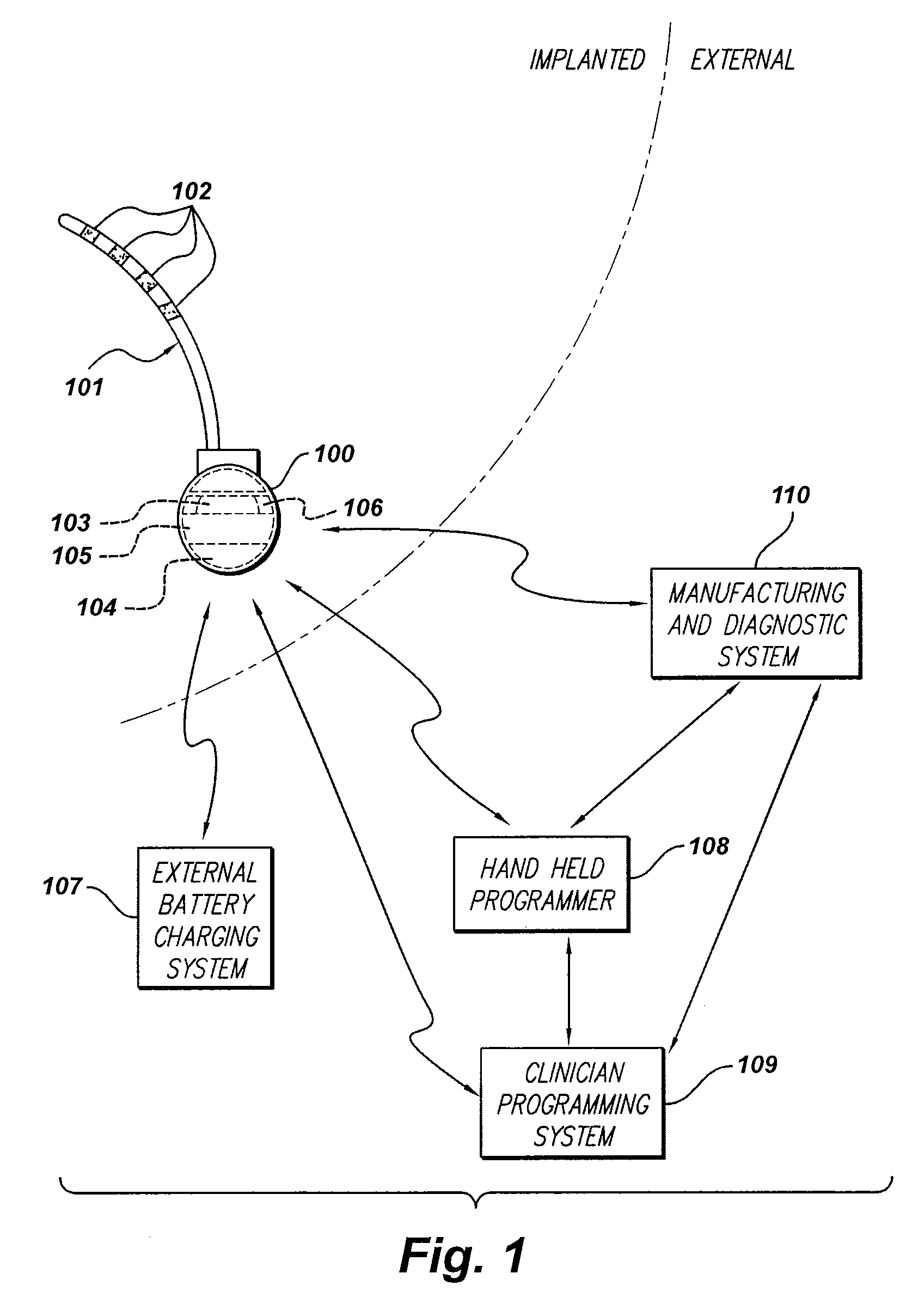
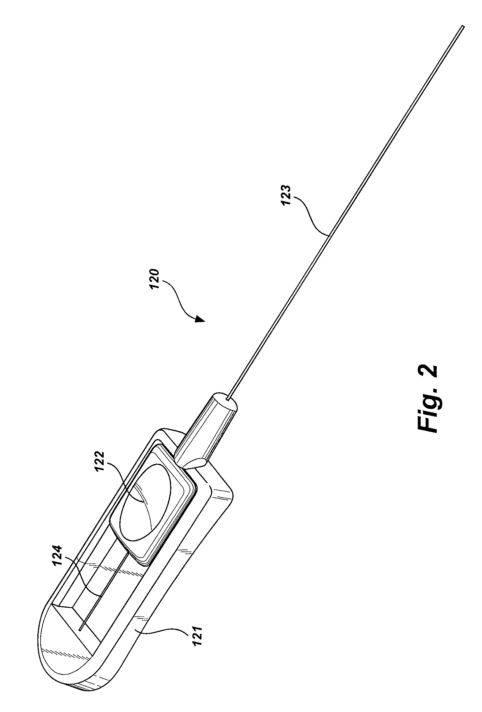
[0018]Exemplary steerable stylet handle assemblies are described herein. In some examples, a steerable stylet handle assembly includes a housing having first and second side walls defining a channel therebetween, a button in communication with the first and second side walls and configured to move distally and proximally within the channel, and a stylet subassembly having an inner stylet wire located at least partially within an outer tubing. The inner stylet wire has a pre-curved portion and is coupled to a proximal portion of the housing. The outer tubing is coupled to the button. Movement of the button within the channel is configured to selectively expose and cover at least a portion of the pre-curved distal portion of the inner stylet wire with the outer tubing. In this manner, a physician or other handler may more easily and precisely position a stimulating member (e.g., a lead or a catheter) at a stimulation site within a patient.

[0019]In the following description, for purpos...


PUM

PropertyMeasurementUnit
pressureaaaaaaaaaa
electrical stimulationaaaaaaaaaa
flexibleaaaaaaaaaa

Abstract

An exemplary steerable stylet handle assembly includes a housing having first and second side walls defining a channel therebetween, a button in communication with the first and second side walls and configured to move distally and proximally within the channel, and a stylet subassembly having an inner stylet wire located at least partially within an outer tubing. The inner stylet wire has a pre-curved portion and is coupled to a proximal portion of the housing. The outer tubing is coupled to the button. Movement of the button within the channel is configured to selectively expose and cover at least a portion of the pre-curved distal portion of the inner stylet wire with the outer tubing.

Description

CROSS-REFERENCE TO RELATED APPLICATIONS[0001]The present application claims the benefit of U.S. Provisional Patent Application No. 61 / 022,953, filed Jan. 23, 2008, which is incorporated herein by reference in its entirety.BACKGROUND[0002]Spinal cord stimulation (SCS) is a well-accepted clinical method for treating a variety of medical conditions in certain populations of patients. SCS systems typically include an implantable pulse generator (IPG) and at least one stimulating lead with one or more electrodes disposed thereon. The lead may be implanted epidurally near the patient's spine and the IPG may be implanted in a surgically convenient location (e.g., within a subcutaneous pocket created within the torso of the patient). The IPG may then generate and deliver electrical stimulation pulses via the one or more electrodes to the spine in accordance with stimulation parameters configured to treat a particular medical disorder.[0003]It is often difficult for a physician to properly p...

Claims


Application Information

Patent Timeline
Patent Type & Authority Applications(United States)
IPC IPC(8): A61N1/05A61M5/00B23P11/00
CPCA61B17/06109A61B17/3468A61B2017/003Y10T29/49826A61N1/0551A61N1/37264A61N1/3787A61B2017/00331
Inventor BARKER, JOHN MICHAEL
Owner BOSTON SCI NEUROMODULATION CORP
Why Eureka
Try Eureka