Method and system for locating landmarks on 3D models

a landmark and 3d model technology, applied in the field of landmark and 3d model locating, can solve the problems of complex processing and comparing the 3d models produced by imaging devices, difficult object object comparison, and requiring 30 minutes for each human body

Inactive Publication Date: 2009-07-23
NAT RES COUNCIL OF CANADA
View PDF10 Cites 11 Cited by
  • Summary
  • Abstract
  • Description
  • Claims
  • Application Information

AI Technical Summary

Benefits of technology

[0011]computer readable program code means for causing a computer to determine a surface potential for each of the plurality of landmarks to be attributed to a vertex of the mesh based on the statistical and the spin images for the vertices; computer readable program code means for causing a computer to identify, for each of the plurality of landmarks, a set of the vertices having the highest surface potential; computer readable program code means for causing a computer to determine a 3-dimensional translation for each pair of vertices from two of the sets corresponding to a pair of neighboring landmarks; computer readable program code means for causing a computer to determine a 3-dimensional translation potential for each pair of neighboring landmarks to be one of the pairs of vertices based on the statistical model and the 3-dimensional translations for each pair of vertices; computer readable program code means for causing a computer to perform probabilistic inferencing to maximize the surface potential and the 3-dimensional translation potential for each of the plurality of landmarks, wherein the vertex with the highest simplified surface potential and the highest 3-dimensional translation potential for a landmark is assigned to that landmark for the mesh.

Problems solved by technology

However, such objective comparison between models of different objects can be difficult since correspondence between various 3D models for objects in a same category of shapes is not easily determined.
In reality, processing and comparing the 3D models produced by the imaging devices is complicated due to the large amount of data provided by the 3D models, which are often in the form of a mesh with a large number of points on the surface of the model that are connected together.
However, markers are placed on the anatomical landmarks on the human body by an anthropometrist prior to scanning; a tedious process requiring about 30 minutes for each human body.
Efforts made to automate the identification of landmarks on 3D models have produced results that are highly inaccurate.

Method used


Image

  • Method and system for locating landmarks on 3D models
  • Method and system for locating landmarks on 3D models
  • Method and system for locating landmarks on 3D models

Examples


Embodiment Construction

[0020]The following detailed description of the embodiments does not limit the implementation of the embodiments to any particular computer programming language. The computer program product may be implemented in any computer programming language provided that the operating system provides the facilities that support the requirements of the computer program product. An embodiment may be implemented in the C or C++ computer programming language (or may be implemented in other computer programming languages in conjunction with C / C++) or any other such language. Any limitations presented would be a result of a particular type of operating system, computer programming language, or processing system and would not be a limitation of the embodiments described herein.

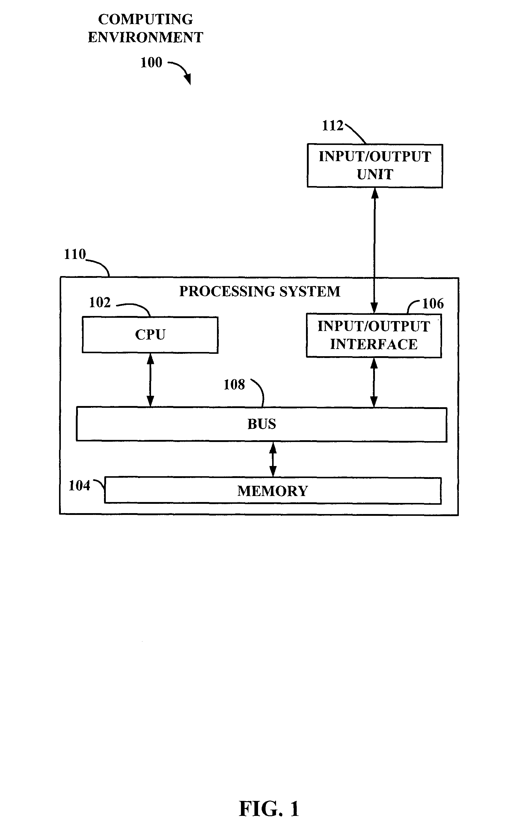
[0021]FIG. 1 illustrates a configuration of a computing environment 100 comprising a processing system 110 in which an embodiment of a system for locating landmarks in a 3D model may be implemented.

[0022]The processing system 1...


PUM


Abstract

A plurality of landmarks are automatically located on a 3-dimensional polygonal mesh of connected vertices. A probabilistic graph is generated for the plurality of landmarks pre-identified on each of a first set of 3-dimensional models. The graph represents local surface characteristics for each landmark and relational positions between neighboring pairs of landmarks. Local surface characteristics are determined for each vertex of the mesh. For each landmark, a set of the vertices is identified that satisfies a criteria based on a surface difference between the vertex local surface characteristics and the landmark local surface characteristics. A relational position for each pair of vertices from the sets of vertices corresponding to the neighboring pairs is determined based on the graph. One of the vertices is determined for each of the plurality of landmarks to minimize the surface difference and the relational difference for the landmark.

Description

BACKGROUND ART[0001]3-dimensional (3D) imaging and measuring devices capture information from the surface of an object in order to create a 3D representation or model of the object. These 3D models enable different objects to be objectively measured, compared, recognized and quantitatively described. However, such objective comparison between models of different objects can be difficult since correspondence between various 3D models for objects in a same category of shapes is not easily determined. Examples of these categories include human faces and bodies, animals of the same family, etc. Although the exact shape of objects from the same category will vary, there is a common structure shared among all of these objects.[0002]In reality, processing and comparing the 3D models produced by the imaging devices is complicated due to the large amount of data provided by the 3D models, which are often in the form of a mesh with a large number of points on the surface of the model that are...

Claims


Application Information

Patent Timeline
Patent Type & Authority Applications(United States)
IPC IPC(8): G06F17/10G06V10/84
CPCG06K9/00214G06K9/00221G06K9/6296G06K9/6211G06K9/00362G06V20/653G06V40/16G06V40/10G06V10/757G06V10/84G06F18/29
Inventor SHU, CHANGAZOUZ, ZOUHOUR BEN
Owner NAT RES COUNCIL OF CANADA
Why Eureka
Try Eureka