Gas meter

a gas meter and gas meter technology, applied in the field of gas meter, can solve the problems of large pressure loss, difficult to detect accurately, and inability to measure, and achieve the effect of good accuracy, easy measurement and risk-free pressure loss

Inactive Publication Date: 2009-07-30
YAMATAKE HONEYWELL CO LTD
View PDF9 Cites 22 Cited by
  • Summary
  • Abstract
  • Description
  • Claims
  • Application Information

AI Technical Summary

Benefits of technology

[0017]In the gas meter of the basic structure set forth above, a contaminant-removing filter is preferably provided in only the first flow path that is provided for the flow rate measurement, so there is no change, due to the adhesion of contaminants, to the detection characteristics of the flow rate sensor that is provided in the first flow path. Furthermore, the first and second flow paths, wherein the flow rates sensors are provided, have a larger flow of the gas to be measured in the minute flow rate because the partial flow in respect to the third flow path is higher when the flow rate of the gas to be measured, which is flowing through the main flow path, is small, and when the flow rate of the gas to be measured, which is flowing through the main flow path, is large, then the partial flow rate in respective the third flow path is lower, preventing the passage of a large flow rate of the gas to be measured. Consequently, the provision of the respective flow rates sensors of the first and second flow paths, that act in this way, enables easy measurement, with good accuracy, over a broad range from minute flow rates, such as gas leaks, to the large flow rates of the normal state of use of the gas.
[0018]Furthermore, the flow path cross-sectional areas of the first flow path, which is provided for the flow rate measurement, and the second flow path, which is provided for detecting the leakage flow rate, are adequately narrow when compared with the flow path cross-sectional area of the third flow path, resulting in nearly all of the gas to be measured passing through the third flow path that has the large partial flow rate, making it possible to incorporate a contaminant-removing filter in the first flow path without the risk of problems with pressure loss. Consequently, measurements of the flow rates of the gas to be measured can be performed with good accuracy in a state that is always clean.
[0019]Note that in the second flow path, it is adequate to be able to detect only whether or not a leakage flow rate exists, and there is no need to increase the measurement accuracy by providing the contaminant-removing filter described above. Consequently, there is no difficulty with the pressure loss due to the existence of the contaminant-removing filter that is provided in the first flow path, or the minute flow rate of the gas to be measured, resulting from a gas leak, being impeded thereby and thus flowing into the second flow path. The result is that it is possible to detect with good reliability and high accuracy the flow rate of the gas to be measured in the first flow path, while possible to detect reliably a gas leak with a minute flow rate in the second flow path.
[0020]Given the structure set forth above, the flow rates sensors that are built into the first and second flow paths do not become saturated, due to the existence of the third flow path, enabling integrated detection over a broad range, from a minute flow rate to a large flow rate.
[0021]Note that after securing a supplemental interval relative to the flow of the gas to be measured, a narrow width portion, wherein the flow path cross-sectional area is constricted, is preferably provided in the second flow path, and by building the flow rate sensor into this narrow width portion it is possible to increase the flow velocity of the minute flow rate that flows in the second flow path at the narrow width portion. The result is that it is possible to essentially increase the sensitivity of detection of the flow rate sensor, making it possible to detect minute flow rates easily. In particular, because the narrow width portion also functions to add resistance to the flow path for a large flow rate, it functions with the effect of passively changing the partial flow ratio in relation to the third flow path.

Problems solved by technology

However, when the detection sensitivity is increased for a minute flow, through the means described above, the detection sensitivity is also increased for a large flow rate commensurately, saturating the output of the flow rate sensor when there is a large flow rate, and thus there is a problem in that the measurement is not possible when there is a large flow rate.
For this reason, it is difficult to detect accurately down to a minute leakage flow rate of about 5 liters per hour (l / h) in a gas meter for, for example, a maximum measurable flow rate of 30,000 l / h.
However, in low-pressure gas meters wherein the supply pressure of the gas to be measured is about 2 Kilopascals (kPa), the allowable pressure loss is about 200 Pascals (Pa) at the most, and thus there are problems in providing a dust-removing filter wherein there is a large pressure loss.
In particular, in a so-called small-mesh dust-removing filter wherein the dust capture ratio is high, the pressure loss is large, and thus it is still difficult to incorporate these into a low-pressure gas meter as described above.

Method used


Image

  • Gas meter
  • Gas meter
  • Gas meter

Examples


Embodiment Construction

[0031]A gas meter as set forth in the present invention will be described below in reference to the drawings.

[0032]A listing of some of the reference numerals that are used in the drawings, together with descriptions of the corresponding elements, is provided below.

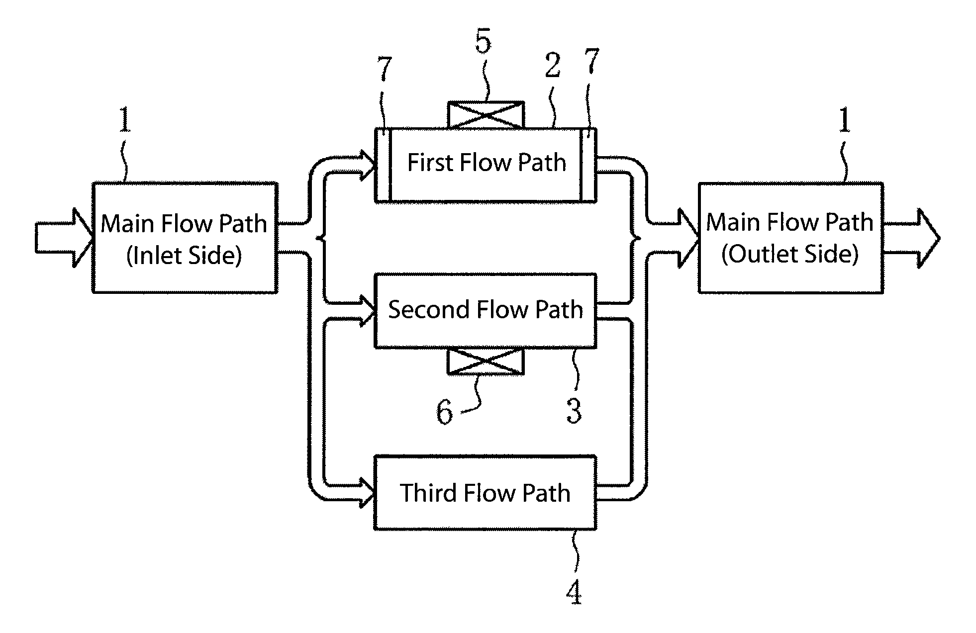
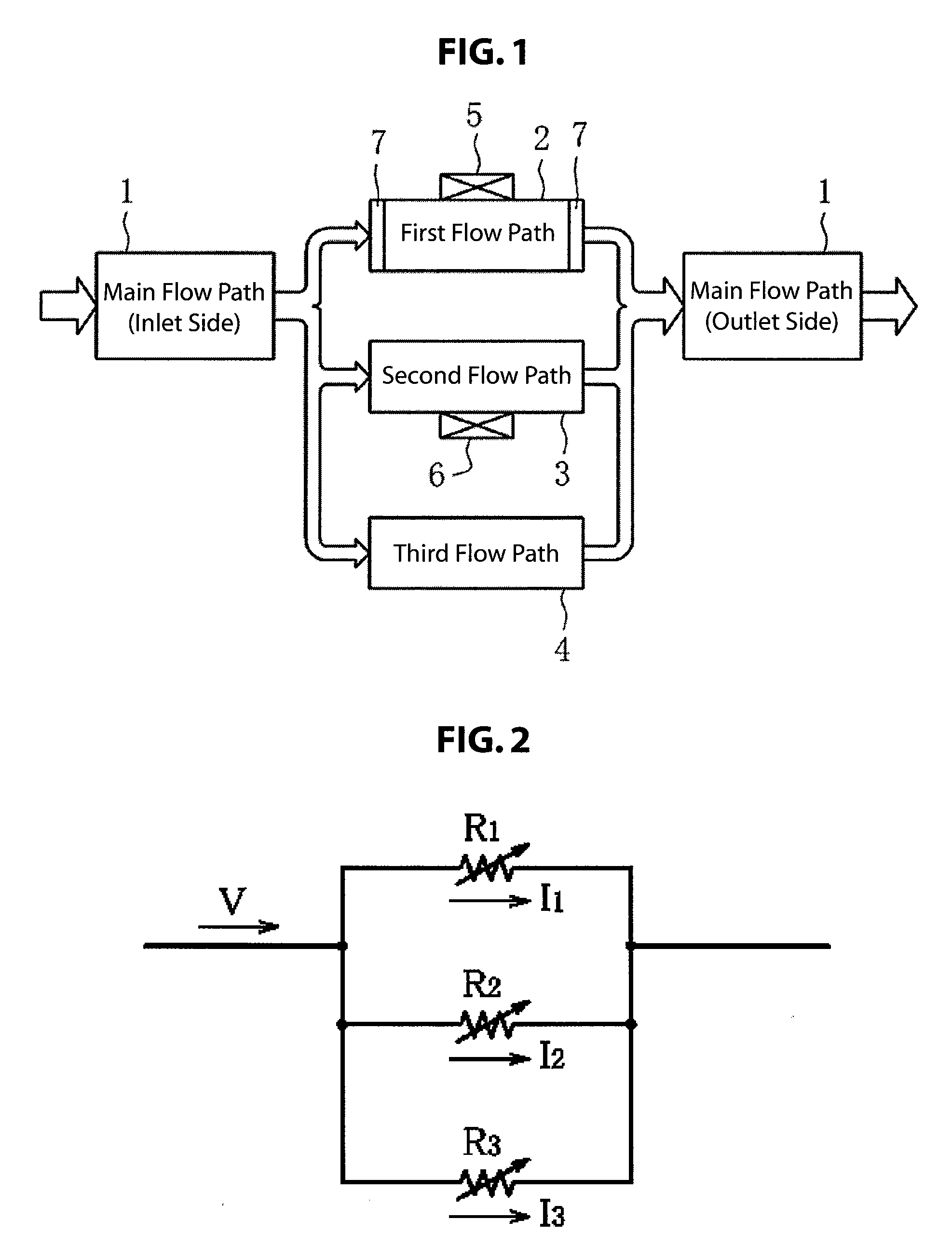
[0033]1: Main Flow Path

[0034]2: First Flow Path (For Flow Rate Measurement)

[0035]3: Second Flow Path (For Leakage Detection)

[0036]4: Third Flow Path

[0037]5, 6: Flow Rate Sensors

[0038]11: Ducting

[0039]12: Lattice Unit

[0040]13, 14: Minute Flow Paths

[0041]15: Mesh Unit (Wire Mesh)

[0042]16a: Low flow rate sensor (For Leakage Detection)

[0043]16b: High flow rate sensor (For Flow Rate Measurement)

[0044]17: Mesh Unit (Wire Mesh)

[0045]17a: Mesh Missing Portion

[0046]18a, 18b: Dust Filters (Contaminant-removing Filters)

[0047]A gas meter structured in accordance with the present invention uses a thermal flow sensor for detecting the mass flow rate of, for example, the gas to be measured. Although not illustrated explicitly, this ther...


PUM


Abstract

A gas meter with a simple structure for detecting a range from a minute flow rate, such as a gas leak, to the large flow rate of the normal state of use of the gas, while protecting the flow rate sensor from dust and without producing the problem of pressure loss. First, second, and third flow paths for carrying partial flows of a gas to be measured, in accordance with the flow rate, are provided by partitioning, in parallel, the cross-sectional surface of a main flow path. A flow rate sensor for flow rate measurement is provided in the first flow path with a small flow path cross-sectional area, and a flow rate sensor for detecting a gas leak is provided in the second flow path with a small flow path cross-sectional area, where a flow baffling filter is provided on one end side or both ends of the first and second flow paths, and a contaminant (dust) removing filter is provided on one end side or both ends of the first flow path.

Description

CROSS-REFERENCE TO RELATED APPLICATION[0001]This application claims priority from Japanese Patent Application No. 2008-13635, filed Jan. 24, 2008, which is incorporated by reference herein in its entiretyFIED OF THE INVENTION[0002]The present invention relates to a gas meter with a simple structure capable of measuring with high accuracy and good reliability the flow rate of a gas to be measured, while protecting the flow rate sensor from dust.BACKGROUND OF THE INVENTION[0003]A gas meter that uses a thermal flow sensor has been proposed wherein the speed of flow is increased at the position of a wall surface by partitioning, into a plurality of parallel minute flow paths, in the direction of flow of a fluid, the internal portion of a flow path wherein the a flow rate sensor has been attached to the wall surface, and a nozzle portion is provided in the middle of the flow path, to thereby increase the speed of flow at the nozzle portion, to thereby increase the detection sensitivity a...

Claims


Application Information

Patent Timeline
Patent Type & Authority Applications(United States)
IPC IPC(8): G01M3/04
CPCG01F1/6842G01F5/00G01M3/26G01F15/125G01F15/028
Inventor OOISHI, YASUHARU
Owner YAMATAKE HONEYWELL CO LTD
Why Eureka
Try Eureka