Induction heated server and method of making

a technology of induction heating and servers, applied in the field of induction heating servers, can solve the problems of high internal pressure, 0 percent latent storage, and 100 percent sensible heat in the metal plate,

Inactive Publication Date: 2009-07-30
NEWSTAR BUSINESS CREDIT +1
View PDF15 Cites 24 Cited by
  • Summary
  • Abstract
  • Description
  • Claims
  • Application Information

AI Technical Summary

Benefits of technology

[0014]It has now been found that the foregoing and related objects may be readily attained in an induction heatable server comprising a bottom element having a bottom wall and a peripheral wall defining an upwardly opening cavity in which are disposed a heat retentive disc or load. A top element having a dependent peripheral flange extends over the heat retentive disc and seals the cavity. The base element is overmolded with resin about the heat retentive disc and has a generally horizontal flange which extends over a peripheral portion of the top element. As a result, the heat retentive disc is encapsulated and the top element is bonded to the peripheral wall of the base element to preclude moisture penetration into the cavity.

Problems solved by technology

This is a challenge in food service applications where meals are delivered to remote locations such as in hospitals and nursing homes.
A disadvantage of the Aladdin technology is that the thermal storage in the metal plate is 100 percent sensible heat and 0 percent latent storage.
The Aladdin system is not capable of storing energy to the same level as the Dinex server without using a heavy and costly metal load that operates at temperatures in excess of 500° F. Because of the high temperature, air trapped inside the Aladdin server expands and creates a high internal pressure.
A pressure relief valve is provided to vent the high pressure air or moisture that, if not otherwise relieved, could create an unsafe condition.
The reliability of the Aladdin system is diminished by failure of the pressure relief valve which itself can result in water infiltration during the washing process.
However, the reliability of this Dinex server is compromised by the need to ultrasonically weld the upper and lower plastic elements together.
Experience has shown that the weld seam is not reliable, and water can infiltrate the induction zone during washing when the seal is not 100 percent hermetic.
When this happens, the server loses its ability to keep the food warm.

Method used


Image

  • Induction heated server and method of making
  • Induction heated server and method of making
  • Induction heated server and method of making

Examples


Embodiment Construction

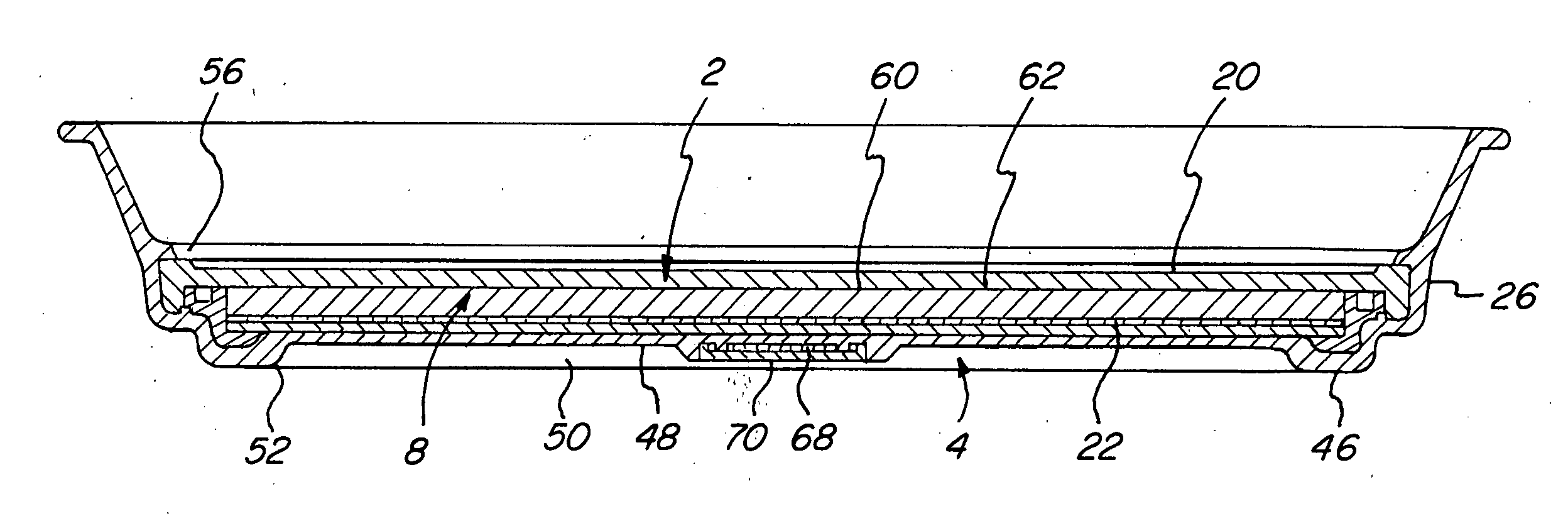
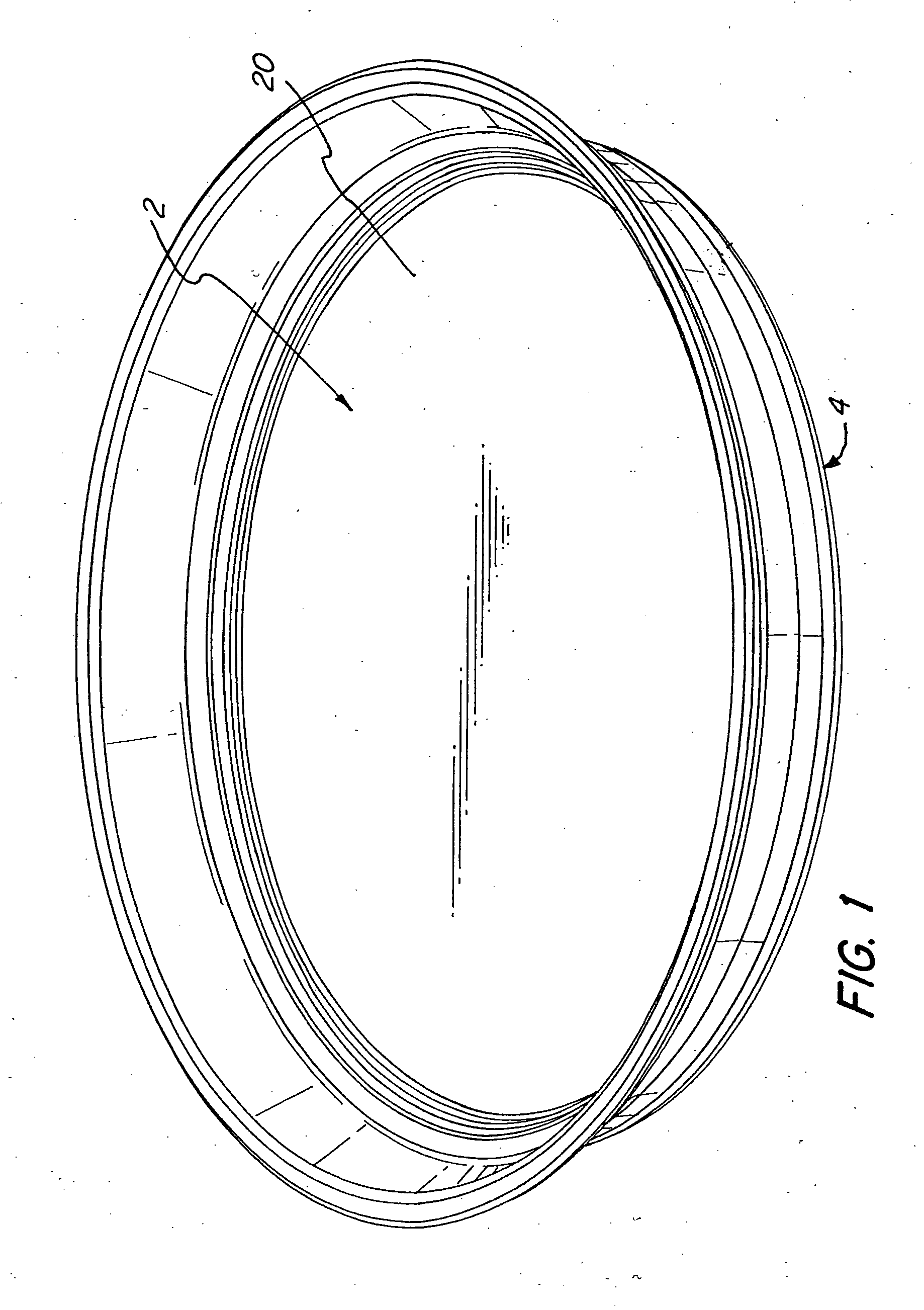
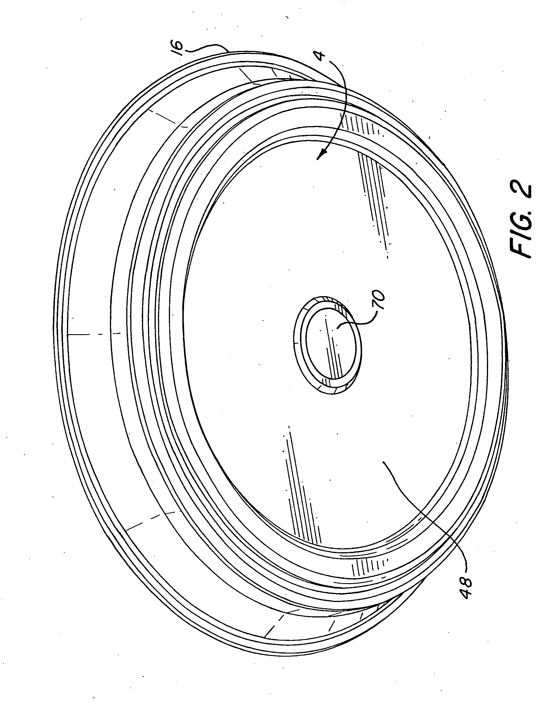
[0033]Turning first to FIGS. 1, 2, 6, and 10, therein illustrated is a server embodying the present invention comprised of a top element generally designated by the numeral 2, a bottom element generally designated by the numeral 4, an RFID tag 68 seated in a well 66, and a cap 70 sealing the tag 68 in the well.

[0034]The components which are internal to the assembled top and bottom elements 2, 4 comprise a perimeter ring (“P-ring”) 14, the disc or load 8, insulation 10, high temperature resin film 12, and a layer of vermiculite 22. These internal elements are assembled in a mold cavity with the previously molded top element 2, and molten resin is injected into the mold cavity to overmold the bottom element 4 and encapsulate the internal elements to bond to the top element 2 and P-ring 14.

[0035]The new induction heated server design and assembly process was developed to address the limitations of the current base technology. The new server encapsulates the load in an overmolding proce...


PUM

PropertyMeasurementUnit
temperaturesaaaaaaaaaa

Abstract

An induction heatable server comprises a base element having a bottom wall and a peripheral wall defining an upwardly opening cavity in which are disposed a heat retentive disc and a ring member which is bonded to the peripheral wall. A top element extends over the ring member and seals the cavity. The top element is bonded to the peripheral wall of the base element and the ring member to preclude moisture penetration into the cavity.

Description

BACKGROUND OF THE INVENTION[0001]The present invention relates to induction heated servers for heating and / or maintaining the temperature of food in serving plates placed thereon.[0002]Food must be served at temperatures above 140° F. to maintain good taste and quality. This is a challenge in food service applications where meals are delivered to remote locations such as in hospitals and nursing homes. Meals are served on china plates or serving dishes in a central kitchen and then transported to patients in their rooms. To keep the food warm, the served food is placed on a special heated “base” or server and then covered with an insulated dome. Typically, the food temperature must be held above 140° F. for up to 1 hour.[0003]The special base or server is itself heated by an electromagnetic induction process. The base assembly includes an encapsulated “load” or heat retentive disc which is (1) susceptible to electromagnetic excitation and converts electromagnetic energy into equival...

Claims


Application Information

Patent Timeline
Patent Type & Authority Applications(United States)
IPC IPC(8): H05B6/12B23P19/04
CPCA47J27/002Y10T29/5313A47J36/24A47J36/02
Inventor JONES, BRIAN C.GOYETTE, GLENN H.BELAND, ALBERT J.RUNYAN, RICHARD C.
Owner NEWSTAR BUSINESS CREDIT
Why Eureka
Try Eureka