Movable body drive system, pattern formation apparatus, exposure apparatus and exposure method, and device manufacturing method

a drive system and moving body technology, applied in the direction of photomechanical equipment, instruments, printers, etc., can solve the problems of low precision, difficult to manufacture grid plates with a large area and high precision, and almost unrealistic especially in terms of cost, so as to achieve high precision and high-precision exposure

Inactive Publication Date: 2009-07-30
NIKON CORP
View PDF33 Cites 61 Cited by
  • Summary
  • Abstract
  • Description
  • Claims
  • Application Information

AI Technical Summary

Benefits of technology

[0025]With this method, based on the output of the two-dimensional head that faces the scale, positional information of the movable body in at least directions of two degrees of freedom within the predetermined plane including the first and second directions is computed, and based on the computed positional information, the movable body is driven along the predetermined plane. Accordingly, th

Problems solved by technology

However, since it is difficult to manufacture the grid plate with a large area and high precision as is disclosed in the U.S. Patent Application Publication described above, a plurality of grid plates needed to be placed side by side

Method used


Image

  • Movable body drive system, pattern formation apparatus, exposure apparatus and exposure method, and device manufacturing method
  • Movable body drive system, pattern formation apparatus, exposure apparatus and exposure method, and device manufacturing method
  • Movable body drive system, pattern formation apparatus, exposure apparatus and exposure method, and device manufacturing method

Examples


Embodiment Construction

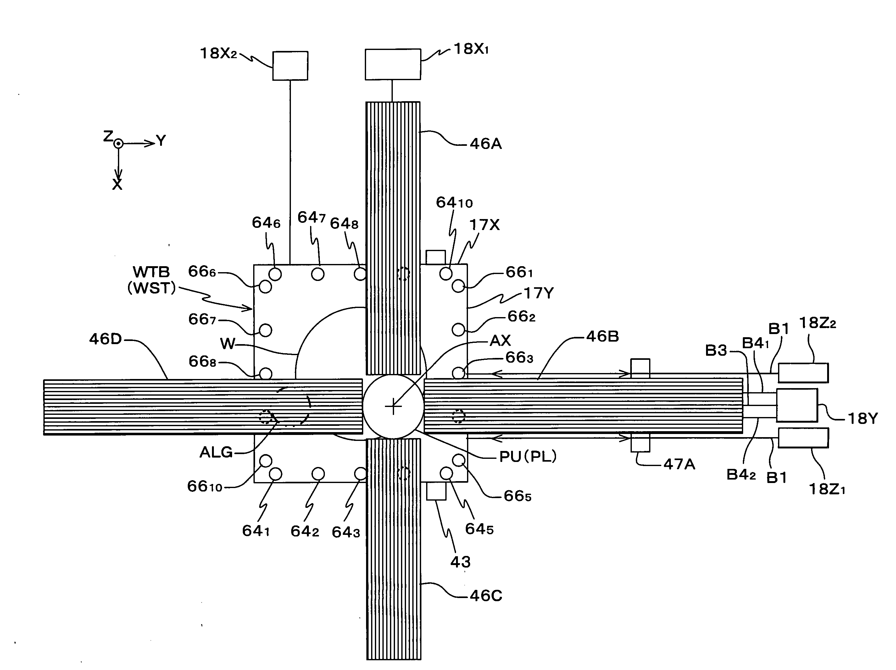
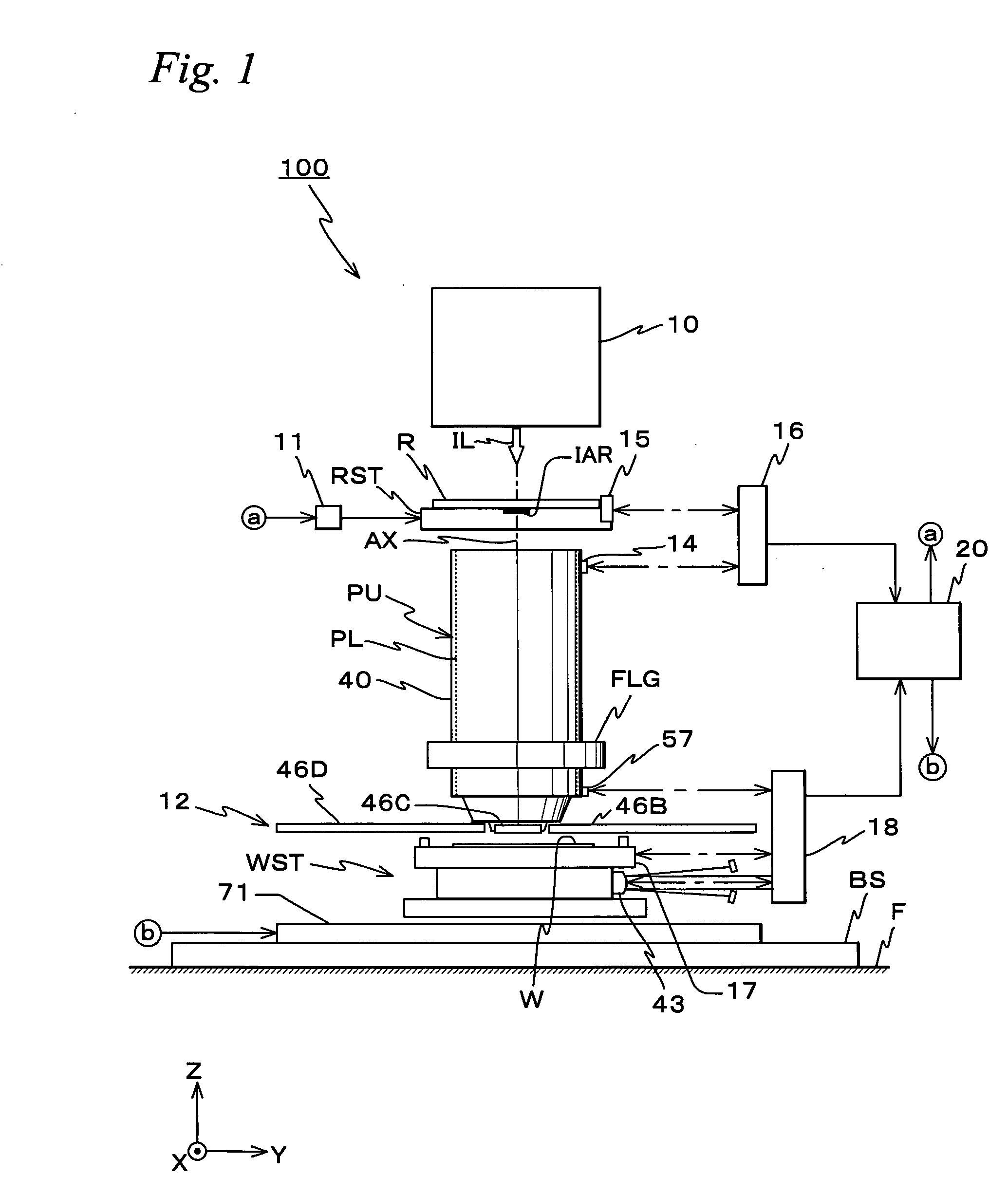
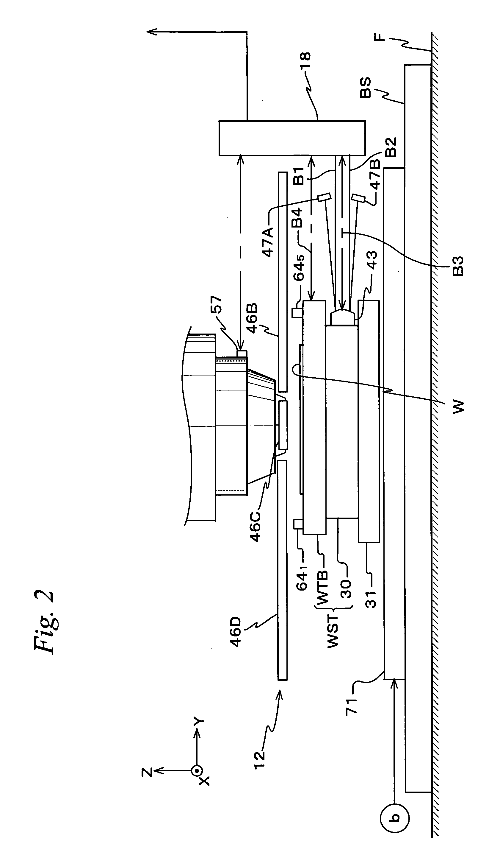
[0039]An embodiment of the present invention is described below, with reference to FIGS. 1 to 7.

[0040]FIG. 1 shows a schematic configuration of an exposure apparatus 100 related to the embodiment. Exposure apparatus 100 is a reduction projection exposure apparatus by a step-and-scan method, which is a so-called scanner. As is described later, a projection optical system PL is provided in this embodiment, and in the description below, the explanation is given assuming that a direction parallel to an optical axis AX of projection optical system PL is a Z-axis direction, a direction in which a reticle and a wafer are relatively scanned within a plane orthogonal to the Z-axis direction is a Y-axis direction, and a direction that is orthogonal to a Z-axis and a Y-axis is an X-axis direction, and rotation (inclination) directions about an X-axis, the Y-axis and the Z-axis are θx, θy and θz directions, respectively.

[0041]Exposure apparatus 100 is equipped with an illumination system 10, a ...


PUM


Abstract

A stage device is equipped with a first scale which is placed with a Y-axis direction serving as its longitudinal direction and in which a first grating whose periodic direction is in an X-axis direction is formed and a second scale which is placed with the X-axis direction serving as its longitudinal direction and in which a second grating whose periodic direction is orthogonal to the periodic direction of the first grating is formed, the first scale and the second scale being placed on a plane which a wafer stage faces. Further, on the upper surface of the wafer stage, a plurality of X heads placed at different positions in the X-axis direction and a plurality of Y heads placed at different positions in the Y-axis direction are arranged. An encoder system that has these heads measures positional information of the stage within an XY plane, based on an output of the X head facing the first scale and an output of the Y head facing the second scale.

Description

CROSS-REFERENCE TO RELATED APPLICATIONS[0001]This non-provisional application claims the benefit of Provisional Application No. 61 / 006,814 filed Jan. 31, 2008, the disclosure of which is hereby incorporated herein by reference in its entirety.BACKGROUND OF THE INVENTION[0002]1. Field of the Invention[0003]The present invention relates to movable body drive systems, pattern formation apparatuses, exposure apparatuses and exposure methods, and device manufacturing methods, and more particularly to a movable body drive system that measures the position of a movable body using an encoder system and drives the movable body substantially along a predetermined plane, a pattern formation apparatus equipped with the movable body drive system, an exposure apparatus equipped with the movable body drive system and the exposure method using the movable body drive system, and a device manufacturing method using the exposure apparatus or the exposure method.[0004]2. Description of the Background A...

Claims


Application Information

Patent Timeline
IPC IPC(8): G03B27/32G03B27/42G01B21/00
CPCG03F7/70775G03F7/70825G03F9/7088G03F9/7015G03F9/7049G03F7/7085G03F7/70716G03F7/70758
Inventor SHIBAZAKI, YUICHI
Owner NIKON CORP
Why Eureka
Try Eureka