Exposure device

A technology of exposure device and exposure chamber, which is applied in the direction of photolithography exposure device, microlithography exposure equipment, electrical components, etc., can solve the problems of high cooling medium price, complex structure, easy adhesion, etc., to maintain lens characteristics, prevent Illumination unevenness, labor-saving effects

Active Publication Date: 2009-08-26
ORC MFG
View PDF3 Cites 2 Cited by
  • Summary
  • Abstract
  • Description
  • Claims
  • Application Information

AI Technical Summary

Problems solved by technology

That is, in the prior art, volatile substances tend to adhere to the fly-eye lens, so there is a problem that the above-mentioned exposure conditions are likely to be lowered.
[0008] The above-mentioned reference document (Patent Document 1) is known as an invention protecting the fly-eye lens, but its structure is complicated, and there are problems such as poor maintenance workability of the fly-eye lens and high cooling medium cost.

Method used


Image

  • Exposure device
  • Exposure device
  • Exposure device

Examples


Embodiment Construction

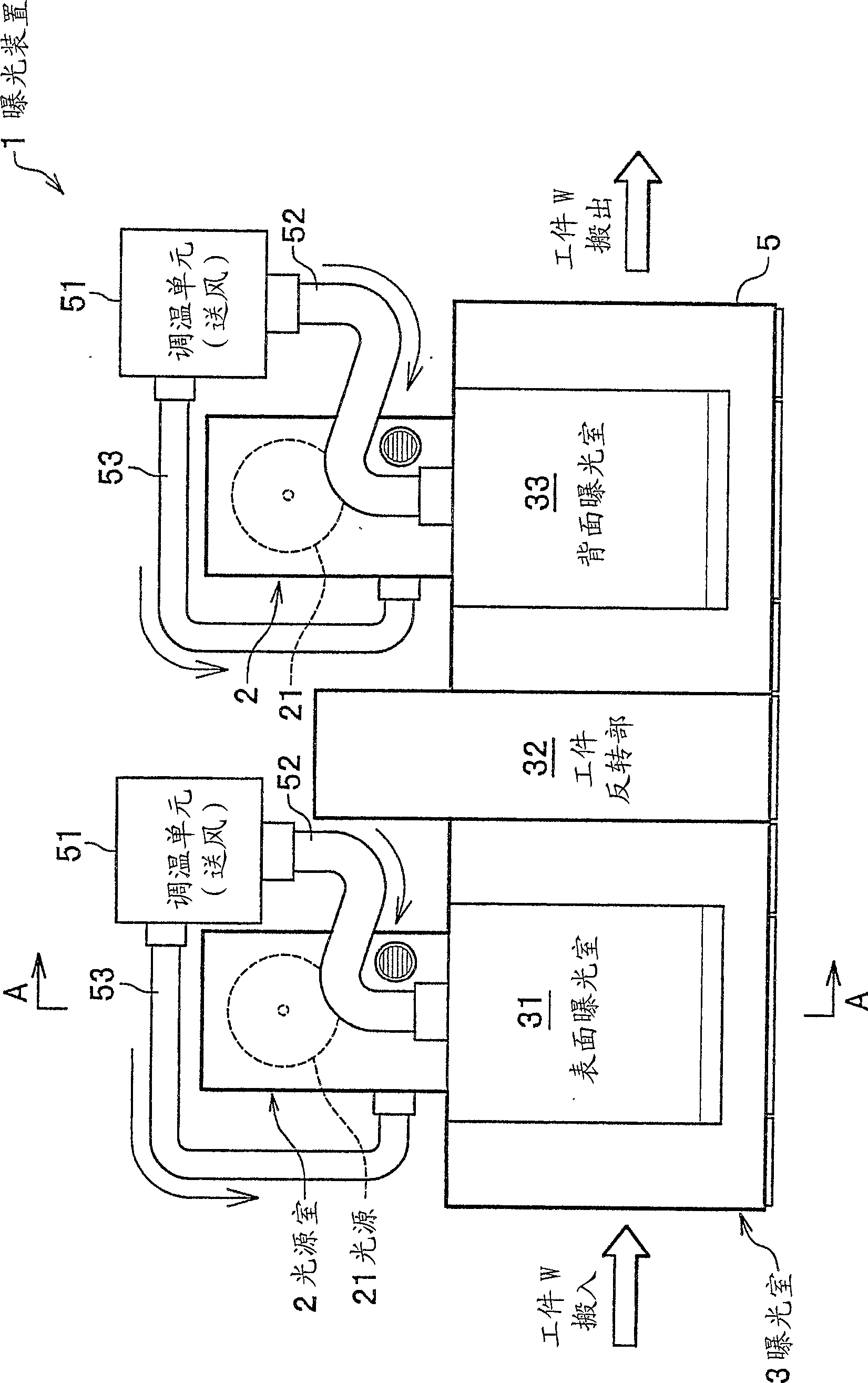
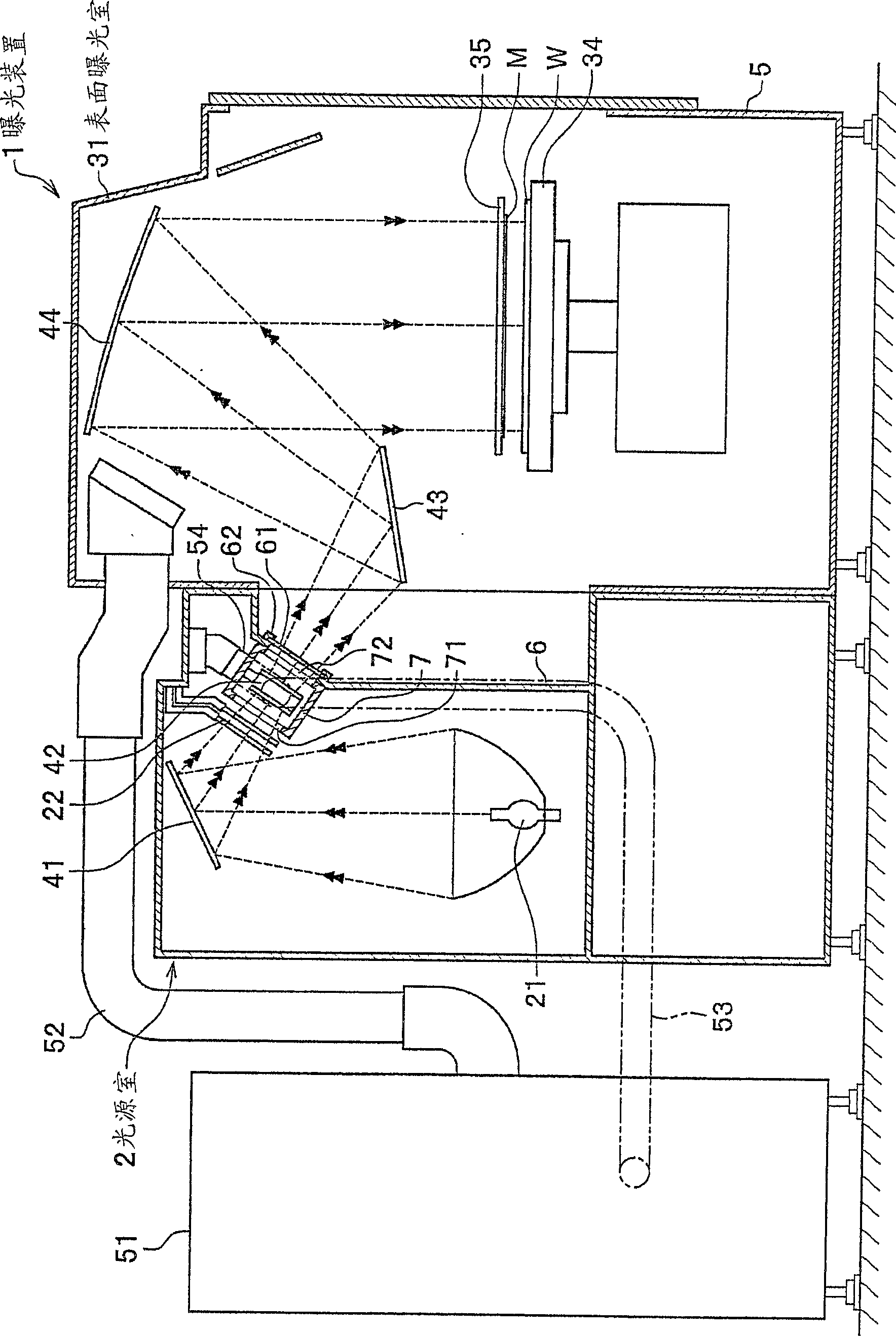
[0049] Next, embodiments of the present invention will be described in detail with reference to appropriate drawings. figure 1 It is a plan view of the overall structure of the exposure apparatus of this embodiment. figure 2 for figure 1 A cross-sectional view of the exposure apparatus shown along line A-A. image 3 It is a partially cutaway perspective view of the light source chamber seen from the exposure chamber side.

[0050] Such as figure 1 As shown, the exposure device 1 mainly includes in the cavity (chamber) 5: a light source chamber 2; a processing chamber for exposing the substrate with irradiation light, that is, an exposure chamber 3; Optical system on the road (mirror 41 etc., refer to figure 2 ). A temperature adjustment unit 51 (air blower) is provided in the cavity 5 through a duct 52 attached to the upper portion thereof. The temperature adjustment unit 51 can supply cooling air into the cavity 5 and discharge it. Therefore, a certain air supply pa...


PUM


Abstract

The invention provides an exposure device, which prevents the contamination of the surface of the fly-eye lens caused by the volatile matter produced by the photosensitive resin with a simple structure. The exposure device includes: a light source chamber having a light source, a reflector, and a fly-eye lens; and an exposure chamber separated from the light source chamber through a partition plate, including: a casing for accommodating the fly-eye lens; and an air blower for cooling The wind is sent to the fly-eye lens contained in the above-mentioned casing; the above-mentioned casing has: an opening formed at a position corresponding to the incident light path and the outgoing light path of the light from the above-mentioned light source; the air inlet is formed The above-mentioned blower device is connected at a position perpendicular to the opening direction of the opening; and the exhaust port is formed at a position facing the air intake port, thereby forming a straight line of blowing air in the above-mentioned housing. Path; on the partition plate, a light-transmitting member for transmitting the irradiated light is provided at a position corresponding to the optical path of the irradiated light.

Description

technical field [0001] The present invention relates to an exposure device for exposing a circuit pattern of a mask on a substrate such as a printed circuit board. Background technique [0002] In the exposure device, the light irradiated by the light source passes through the optical system composed of a fly-eye lens and optical components such as a plurality of mirrors, and exposes and develops the circuit pattern formed on the mask on the coating. On the substrate coated with a protective layer (photosensitive resin), to make printed circuit boards, etc. [0003] In general, although the surface of an optical component is covered with an antireflection film, the film is vulnerable to environmental influences due to poor heat resistance. For example, it is well known that sublimated volatile substances generated when a protective layer (photosensitive resin) applied to a substrate undergoes a chemical change adhere to a fly-eye lens used in an exposure device, and the lik...

Claims


Application Information

Patent Timeline
Patent Type & Authority Patents(China)
IPC IPC(8): G03F7/20H01L21/027
Inventor 水口信一郎伊势胜
Owner ORC MFG
Why Eureka
Try Eureka